
Standard Overview
Get the Standard
IEC 61000-4-3 is a commercial EMC standard that outlines test procedures manufacturers must meet before products are sold. The object of IEC 61000-4-3 is to establish a common reference for a product or device's immunity to electromagnetic radiation. Products must be designed and tested to ensure that they are immune to both intentional transmitters, such as walkie talkies and cell phones, and unintentional RF emitting devices like electric motors and welders. There are 4 basic test levels a product must withstand to pass this test:
| Test Level | Field Strength |
|---|---|
| 1 | 1 V/m |
| 2 | 3 V/m |
| 3 | 10 V/m |
| 4 | 30 V/m |
IEC 61000-4-3 does not suggest that a single test level is applicable over the entire frequency range, and should be tested for the appropriate test level for each frequency range. Testing for general purpose RF emissions covers the 80MHz to 1000MHz frequency range and should be performed without any gaps. For digital radiotelephones and other higher frequency devices, tests should be performed in the 800MHz to 960MHz and 1.4GHz to 6.0GHz frequency ranges. Tests in these ranges do not need to be applied continuously over the entire range, and the ranges may be limited to specific frequencies for compliance with specific operating bands in the country the product will be sold in.
There are four major changes that were made to this standard in the third version to better measure immunity at higher frequency ranges which are now more commonly present:
- First and most importantly, the new harmonic distortion requirement of the test setup must be better than -6dBc. This is to minimize distortion at higher frequency ranges.
- Second, a linearity check must be performed before testing to ensure that the RF amplifier used is not operating in compression.
- Third, the frequency range was extended up to 6GHz as a result of the increased use of these bands by newer electronic devices.
- Lastly, there is a change to the test table material requirement. This was done because materials such as wood can become reflective when exposed to higher frequencies.
Test Equipment Needed
Anechoic Chamber – The chamber must be big enough to house a uniform field with sufficient dimensions to cover the entire EUT.EMI Filters – Though not always necessary, use of filters should not add any additional resonance effects during the test
RF Signal generator(s) - The use of a signal generator must be able to cover the frequency being tested, and multiple generators may be needed if multiple frequencies are being tested. It must also be amplitude modulated by a 1 kHz sine wave with a modulation depth of 80%. Also, the generator must have a manual control or be programmable with frequency-dependent step sizes or dwell times. ATEC offers signal analysis test sytems from leading manufacturers like Keysight, Tektronix and Rohde & Schwarz.
Power Amplifiers – this is used to amplify the signal and provide an antenna drive to the necessary field level. Harmonics must be at least 6dB below the fundamental frequency
Field Generating Antennas – These can be either bi-conical, log periodic, horn or any other linearly polarized antenna system
Isotropic Field Sensor – This must have adequate immunity to the field strength being measured and use a fiber optic link to an indicator outside of the chamber
Equipment to record power levels – usually a computer system
Test Facility
The tests performed to conform to this standard must be done in a shielded enclosure. This is because many countries have laws prohibiting interference to radio communications, and this can arise if not properly shielded. The facility must also have a barrier between the EUT and the test instruments. This will minimize distortion and limit errors in results. Interconnecting wiring that can penetrate the shielded enclosure is used, and this wiring must properly attenuate conducted and radiated emission as well as preserve the integrity of the EUT signal and power responses. It should be noted that anechoic chambers are less effective at lower frequencies.Calibration
Before any tests are performed, the chamber and equipment must be calibrated to make sure they can properly perform the required tests. Calibration will ensure the uniformity of the field over the test sample is sufficient to confirm the validity of the results. When calibration is performed, it is valid as long as the test setup used remains unchanged for testing and should be recalibrated every time the setup is changed. If the setup remains unchanged, calibration should be performed annually. During calibration, the field sensor should be 1 to 3 meters from the antenna, and 16 points of measurement must be performed to validate a uniform field area with a minimum size of 0.5m by 0.5m. The actual UFA should be large enough to cover the EUT. An alternative to this way of calibration is through the use of the constant power calibration method.

Test Setup
Testing should be performed in a configuration that is as close as possible to actual conditions in which the EUT will be used. A metallic grounding plane is not required, but the EUT should be placed on a non-metallic, non-conductive material. Low dielectric constant materials such as polystyrene are recommended. Manufacturer wiring and connectors should be used for the tests. If the required wiring length required for the EUT is less than 3m, then the specified length should be used. If the required length is longer, a minimum of 1m of cable should be exposed to the RF field, and excess cables should be bundled in the center of the cable in lengths of 30-40cm.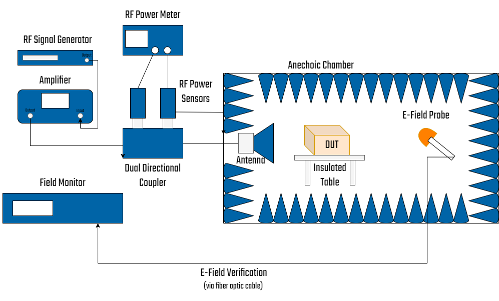_35.png)
Test Procedure
All testing must be performed under normal operating conditions. The test plan should specify:- The size of the EUT
- Operating conditions of the EUT
- Whether tabletop or floor standing
- Type of test facility and position of the antenna
- Type of antenna
- Frequency range, dwell time and frequency steps
- Size and shape of the UFA
- Whether partial illumination is used
- Test level to be applied
- Type and number of interconnecting wires
- Performance criteria
Results
Results should be classified under one of the following definitions:- Normal performance within limits
- Temporary loss of function or degradation of performance which ceases after disturbance ends
- Temporary loss of function or degradation of performance which requires operator intervention for correction
- Non-recoverable loss of performance or degradation
Read More On EMC Testing


, 500 W (4.2 - 6 GHz)")


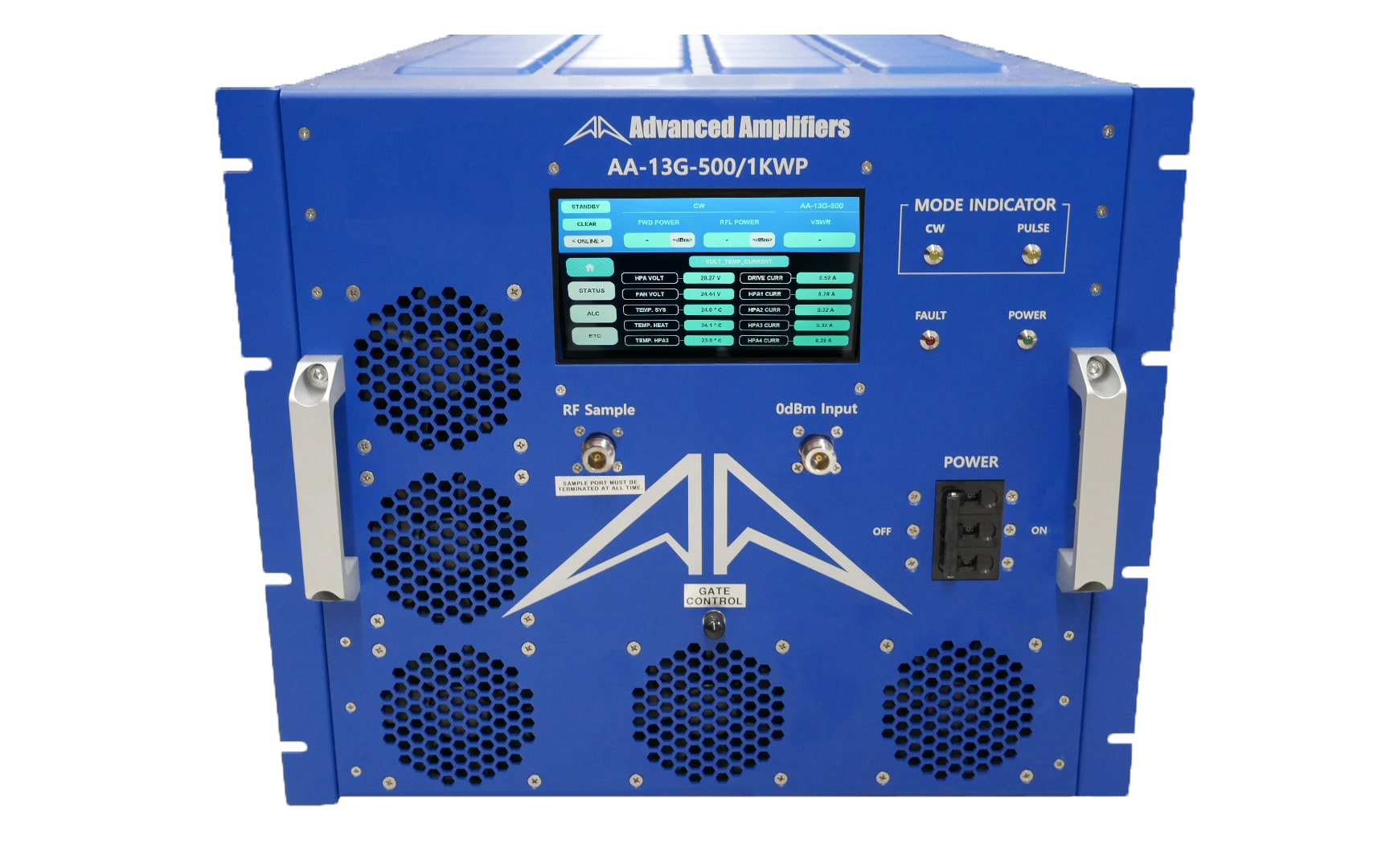-min_24.jpg?width=400 "Advanced Amplifiers AA-13G-500/1KWP")


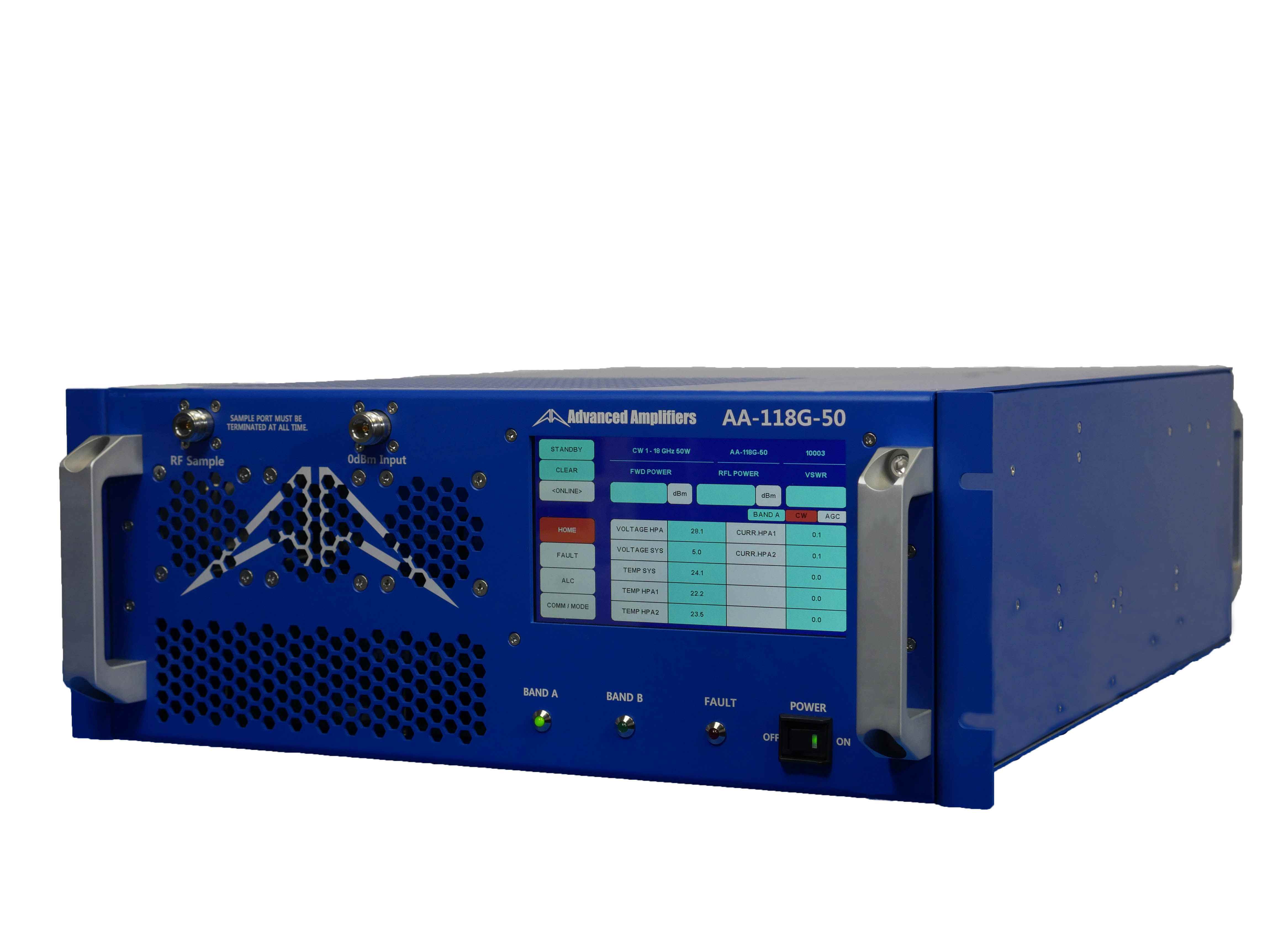_24.jpg?width=400 "Advanced Amplifiers AA-118G-50 Solid-State High Power Amplifier")


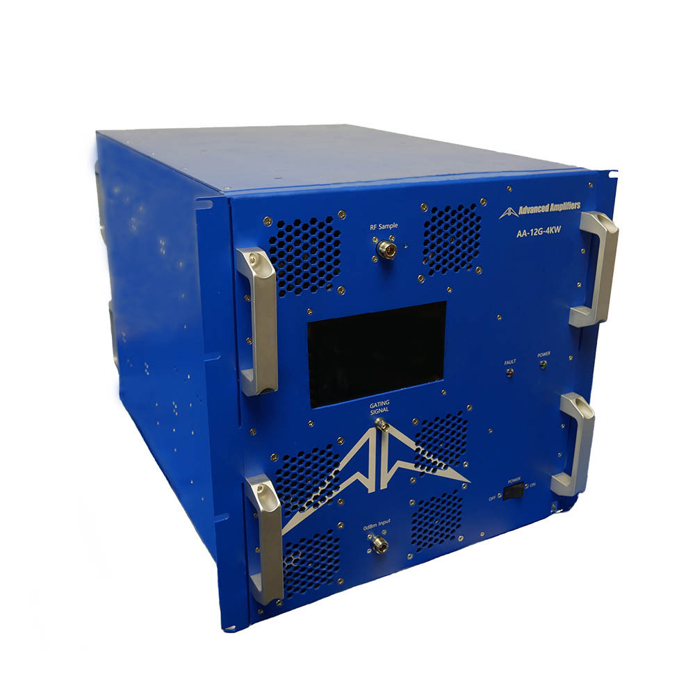-compressed_24.jpg?width=400 "Advanced Amplifiers AA-12G-4KWP")

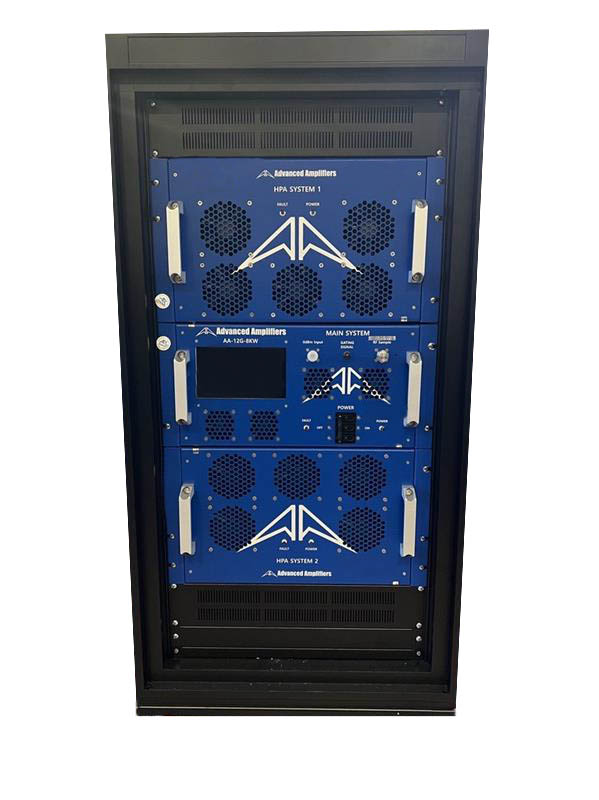_24.jpg?width=400 "Advanced Amplifiers AA-12G-8KWP")

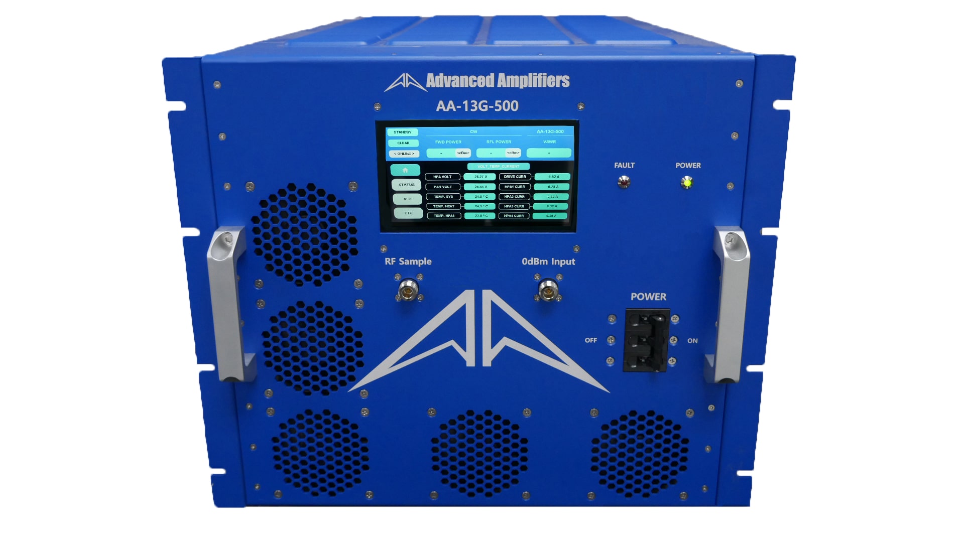-min_24.jpg?width=400 "Advanced Amplifiers AA-13G-500")


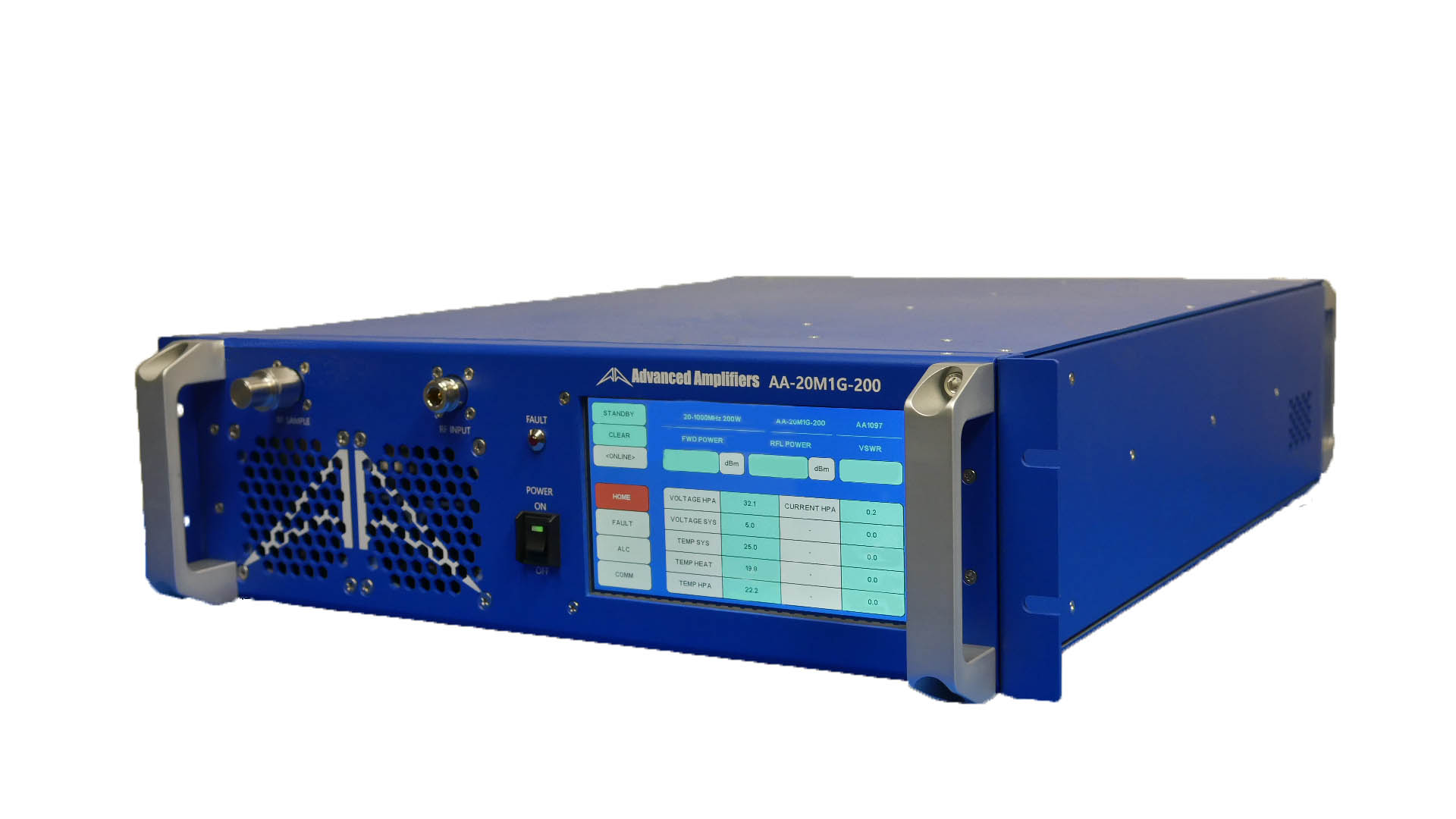_24.jpg?width=400 "Advanced Amplifiers AA-20M1G-200 Solid-State High Power Amplifier")
