
MIL
MIL-STD-461G CS114: Conducted Susceptibility, Bulk Cable Injection
Standard Overview
MIL-STD-461G CS114 applies from 10 kHz to 200 MHz for all interconnecting cables, including power cables. For EUTs intended to be installed on ships or submarines, an additional common mode limit of 77 dBμA applies from 4 kHz to 1 MHz on complete power cables (highs and returns - common mode test).
MIL-STD-461G CS114 does not apply to coaxial cables to antenna ports of antenna-connected receivers except for surface ships and submarines.
MIL-STD-461G CS114 is used to verify the ability of the EUT to withstand RF signals coupled onto EUT associated cabling.
TABLE VI. CS114 Limit Curves
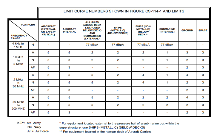
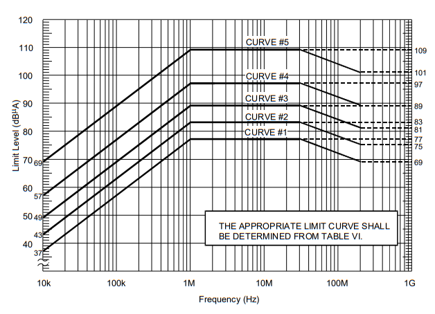
FIGURE CS114-1. CS114 Calibration Limits
_20.png)
FIGURE CS114-2. Insertion Loss for Injection Probes
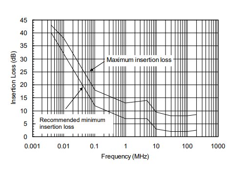
FIGURE CS114-3. Calibration Setup
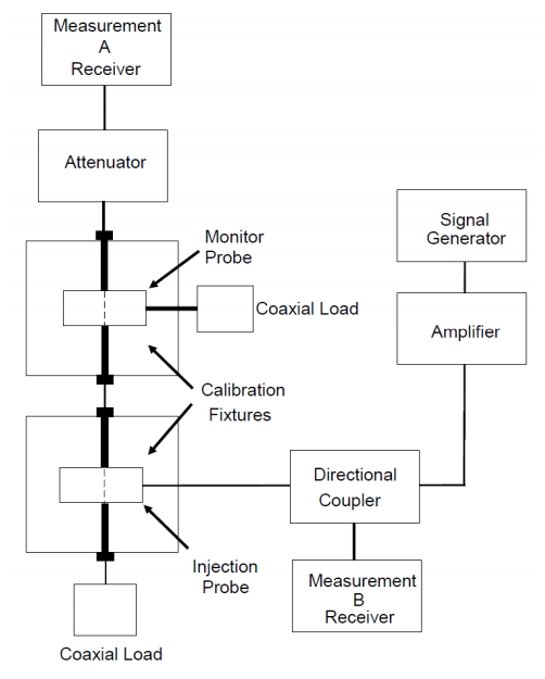
FIGURE CS114-4. Verification Setup

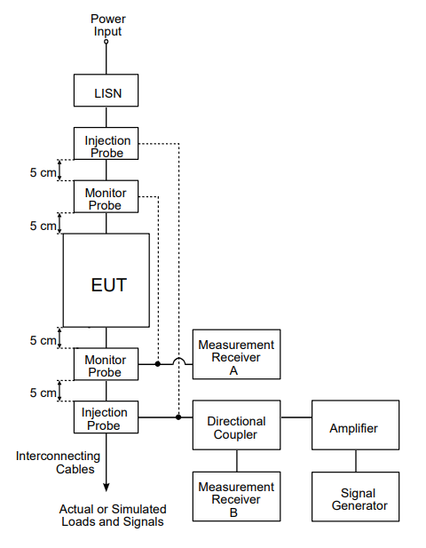
FIGURE CS114-5. Bulk Cable Injection Evaluation
Download Standard
MIL-STD-461G CS114 does not apply to coaxial cables to antenna ports of antenna-connected receivers except for surface ships and submarines.
MIL-STD-461G CS114 is used to verify the ability of the EUT to withstand RF signals coupled onto EUT associated cabling.
Test Equipment
The test equipment shall be as follows:- Measurement receivers
- Current injection probes (maximum and recommended minimum insertion loss shown in Figure CS114-2)
- Current probes
- Calibration fixture: coaxial transmission line with 50 ohm characteristic impedance, coaxial connections on both ends, and space for an injection probe around the center conductor.
- Directional couplers
- Signal generators
- Plotter
- Attenuators, 50 ohm
- Coaxial loads, 50 ohm
- Power amplifiers k. LISNs
Procedures
The test procedures shall be as follows:- a. Turn on the measurement equipment and allow sufficient time for stabilization.
- b. Calibration. Perform the following procedures using the calibration setup.
- (1) Set the signal generator to 10 kHz, unmodulated.
- (2) Increase the applied signal until measurement receiver A indicates the current level specified in the applicable limit exists in the center conductor of the calibration fixture.
- (3) Record the "forward power" to the injection probe indicated on measurement receiver B.
- (4) Scan the frequency band from 10 kHz to 200 MHz and record the forward power needed to maintain the required current amplitude.
- (1) Set the signal generator to 10 kHz, unmodulated.
- c. Verification. With the probes still in the calibration setup, configure the verification of the test system using Figure CS114-4. Conduct a scan as though this is a test of an EUT cable.
- (1) Set the signal generator to 10 kHz (modulation is optional and should not have any effect).
- (2) Apply the forward power level determined under 5.12.3.4b(4) to the injection probe while monitoring the induced current on the monitor probe.
- (3) Scan the required frequency range with minimal dwell times and step sizes twice those in Table II while maintaining the forward power level at the calibrated level determined under 5.12.3.4b(4). Verify that the forward power follows the calibration and that the developed current is within a 3 dB tolerance of the current test limit.
- d. EUT testing. Configure the test as indicated in Figure CS114-5. Perform the following procedures on each cable bundle interfacing with each electrical connector on the EUT including complete power cables (high sides and returns). Also, perform the procedures on power cables with the power returns and chassis grounds (green wires) excluded from the cable bundle. For connectors which include both interconnecting leads and power, perform the procedures on the entire bundle, on the power leads (including returns and grounds) grouped separately, and on the power leads grouped with the returns and grounds removed.
- (1) Turn on the EUT and allow sufficient time for stabilization.
- (2) Susceptibility evaluation.
- (a) Set the signal generator to 10 kHz with 1 kHz pulse modulation, 50% duty cycle. Verify that the modulation is present on the drive signal for each signal generator/modulation source combination. Ensure that the modulation frequency, waveform, and depth (40 dB minimum from peak to baseline) are correct.
- (b) Apply the forward power level determined under 5.12.3.4b(4) to the injection probe while monitoring the induced current. For shielded cables or low impedance circuits, it may be preferable to increase the signal gradually to limit the current.
- (c) Scan the required frequency range in accordance with 4.3.10.4.1 and Table III while maintaining the forward power level at the calibration level determined under 5.12.3.4b(4), or the maximum current level for the applicable limit, whichever is less stringent.
- (d) Monitor the EUT for degradation of performance during testing.
- (e) Whenever susceptibility is noted, determine the threshold level in accordance with 4.3.10.4.3.
- (f) For EUTs with redundant cabling for safety-critical reasons such as multiple data buses, use simultaneous multi-cable injection techniques.
Test Setup
The test setup shall be as follows:- a. Maintain a basic test setup for the EUT as shown and described in Figures 2 through 5 and in 4.3.8.
- b. Calibration. Configure the test equipment in accordance with Figure CS114-3 for calibrating injection probes.
- (1) Place the injection probe around the center conductor of the calibration fixture and the monitor probe around a second fixture. Terminate the monitor probe with a 50 ohm load.
- (2) Terminate one end of the calibration fixture with a 50 ohm load and terminate the other end with an attenuator connected to measurement receiver A.
- c. EUT testing. Configure the test equipment as shown in Figure CS114-5 for testing of the EUT.
- (1) Place the injection and monitor probes around a cable bundle interfacing with an EUT connector.
- (2) To minimize errors, maintain the same signal circuit that was used for calibration between the attenuator at the calibration fixture (oscilloscope, coaxial cables, bulkhead connectors, additional attenuators, etc.) and connect the circuit to the monitor probe. Additional attenuation may be used, if necessary.
- (3) Locate the monitor probe 5 cm from the connector. If the overall length of the connector, backshell or backshell extension exceeds 5 cm, position the monitor probe as close to the connector's backshell or backshell extension as possible.
- (4) Position the injection probe 5 cm from the monitor probe.
TABLE VI. CS114 Limit Curves

FIGURE CS114-1. CS114 Calibration Limits
_20.png)
FIGURE CS114-2. Insertion Loss for Injection Probes

FIGURE CS114-3. Calibration Setup

FIGURE CS114-4. Verification Setup

FIGURE CS114-5. Bulk Cable Injection Evaluation

Download Standard
Products Used in Testing
_17.png?width=400)
Prâna IP-DR250 Bulk Current Injection Probe
- Frequency Range: 10kHz - 400MHz
- Power: 500W (CW), Loss: -33... -6dB
- Inner Diameter: 1.72in (43.8mm)


Vectawave VBA400-110 CW Amplifier | 10 kHz - 400 MHz, 100W
- 10kHz - 400mHz
- 110 Watts
- CW Amplifier


Schloder CDG7000-75-10
- Amp Range: 10kHz - 250/400MHz (25/75W)
- Sig Gen Range: 9kHz - 1.2GHz
- 3 Ports


Teseq CBA400M-110 10kHz-400MHz, 100 Watt RF Amplifier
- 10 kHz - 400 MHz
- 100 W
- 51 dB


Teseq NSG 4070C-80 Test System for Conducted and Radiated Immunity
- Amp Range: 150kHz - 230MHz at 80W
- Sig Gen Range: 4kHz – 1GHz
- 3 Power Meter Ports


Frankonia CIT-1000 Compact Immunity Test System
- Amp Range: 100kHz - 400/250MHz at 75/25W
- Sig Gen Range: 4/9kHz - 1.2GHz
- 3 Power Meter Ports


Amplifier Research 600A400 CW Solid State RF Amplifier | 10 kHz to 400 MHz, 600 W
- 10 kHz to 400 MHz
- 600 W
- - 20 dBc max at 500 W


Amplifier Research 1000A400 Broadband RF Amplifier | 10 kHz - 400 MHz, 1000 W
- 10 kHz - 400 MHz
- 1000 W
- 60 dB


Advanced Amplifiers AA-10K100M-700 Solid State Amplifier
- 10 kHz - 100 MHz
- 1000 W
- 60 dB min


Advanced Amplifiers AA-10k1G-100 Solid State Amplifier
- 10.0 kHz - 1.0 GHz
- 100 W
- 50 dB min


Advanced Amplifiers AA-10K250M-150 Solid State RF Amplifier
- 10 kHz - 250 MHz
- 150 W
- 52 dB min


Advanced Amplifiers AA-10K250M-2500 Solid-State Amplifier
- 10 kHz - 250 MHz
- 2500 W
- 64 dB min

_25.jpg?width=400)
Advanced Amplifiers AA-10K250M-300 Solid-State Amplifier
- 10 kHz - 250 MHz
- 300 W
- 55 dB min


Advanced Amplifier AA-10K250m-500 Solid State RF Amplifier
- 10 kHz - 250 MHz
- 500 W
- 57 dB min


Advanced Amplifiers AA-10M1G-100 Solid State Amplifier
- 10.0 MHz - 1.0 GHz
- 100 W
- 50 dB min


Frankonia CIT-100 Compact Immunity Test System
- Amp Range: 100kHz - 400/250MHz at 75/25W
- Sig Gen Range: 4kHz - 1.2GHz
- 3 Power Meter Ports
