
MIL
MIL-STD-461G CS118: Personnel Borne Electrostatic Discharge (ESD)
Standard Overview
MIL-STD-461G CS118 is the electrostatic discharge testing procedure for conducted susceptibility testing as specified by MIL-STD-461G. The ESD levels, test setup and test equipment of MIL-STD-461G CS118 are similar to IEC 61000-4-2 and RTCA/DO-160. To see the full version of MIL-STD-461G CS118, view MIL-STD-461G.
Advanced Test Equipment Rentals calibrates ESD guns in our lab
For All 30kV Regulated Applications:
TABLE VIII. ESD test levels & Table IX ESD simulator contact discharge current verification values.
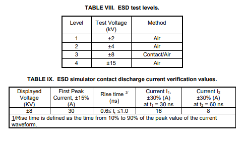
TABLE X. ESD generator general specifications & FIGURE CS118-1
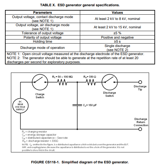
FIGURE CS118-2. Discharge electrodes of the ESD generator & FIGURE CS118-3. Sample ESD current target schematic representation.
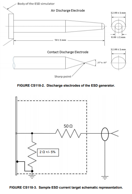
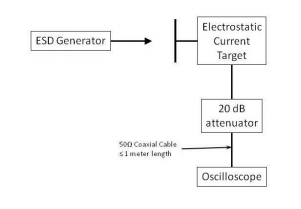
FIGURE CS118-4. Ideal contact discharge current waveform at 8 kV & FIGURE CS118-5. Measurement system check setup, tip voltage verification.
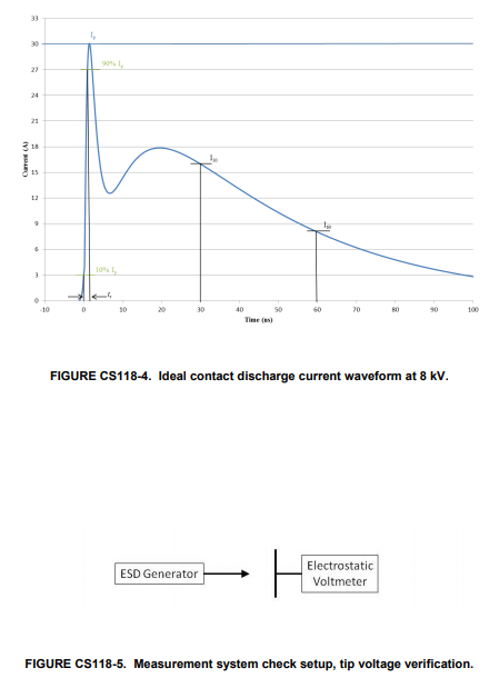
FIGURE CS118-6. Measurement system check setup, discharge current verification.
Advanced Test Equipment Rentals calibrates ESD guns in our lab
Recommended Bundle
For All 30kV Regulated Applications:
 |
+ |
 |
+ |
 |
= |
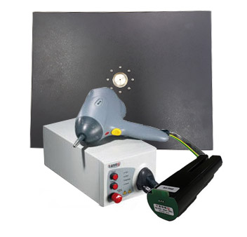 |
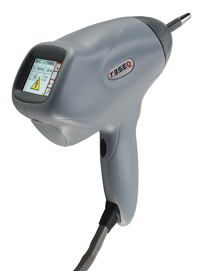
| Teseq NSG 438 ESD Gun Simulator System |
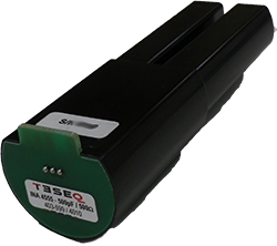
Teseq INA Custom Discharge Network |
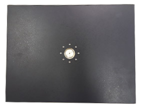
Electro-Tech 949-2 Verification Kit |
ESD Simulator Kit Rent Bundle |
CS118 Applicability
This requirement applies to electrical, electronic, and electromechanical subsystems and equipment that have a man-machine interface. It does not apply to equipment that interfaces with or controls ordnance items.CS118 Limits
The EUT shall not exhibit any malfunction, degradation of performance, or deviation from specified indications, beyond the tolerances indicated in the individual equipment or subsystem specification when subjected to the values shown Table CS118-1. Contact up to 8kV is the required method. Air discharges shall be required only if specified by the procuring activity.Purpose
This test procedure is used to verify the ability of the EUT to withstand personnel borne electrostatic discharge (ESD) in a powered-up configuration:- ESD Simulator Gun
- LISN or other Isolation Transformer
- GP: Ground Reference Plane (Aluminum or Sheet Metal)
- HCP: Horizontal Plane (Aluminum or Sheet Metal)
- VCP: Vertical Coupling Plane (Aluminum or Sheet Metal)
- 470 kOhm Resistor Cables to mount from HCP/VCP to GP
- Insulation Material (Polyvinyl Chloride preferred material)
Test Equipment
The test equipment shall be as follows:- ESD Generator, adjustable from ±2kV to ±15kV (minimum range), see Figure CS118-1 and Table X for simplified ESD generator characteristics.
- ESD network, 150 picofarads (pF) capacitance, 330 ohm discharge resistance.
- Contact discharge tip Figure CS118-2.
- Air discharge tip Figure CS118-2.
- Electrostatic voltmeter.
- Oscilloscope, single event bandwidth ≥ 1 GHz.
- ESD current target, input resistance 2 ±5% ohms, Figure CS118-3.
- Attenuator, 20 dB.
- Coaxial cable, 50 ohm impedance, ≤ 1 meter.
- Metallic ground plane.
- Ionizer or one (1) megohm resistor (1MΩ±10%).
Procedures
The test procedures shall be as follows:- a. Maintaining ESD Generator’s ground strap length used in 5.16.3.3c, ground the ESD Generator to the EUT’s chassis ground point in the test setup.
- b. The EUT shall be powered and operating during this test in a manner sufficient to verify its operation.
- (1) Set the ESD generator’s tip voltage to the selected test level as specified in Table VIII.
- (2) Apply five (5) positive discharges and five (5) negative discharges to each EUT test point as discussed in test point selection in 5.16.3.3 (b).
- (3) Apply the discharges using the following techniques:
- (a) For contact discharges, place the ESD simulator tip directly on the test point and discharge the ESD simulator.
- (b) For air discharges, start at a distance from the test point where no discharge occurs as the ESD simulator is energized, and slowly move the tip perpendicular towards the test point at a rate no faster than 0.3 m per second (0.3m/sec) until the discharge occurs or the tip physically contacts the test point. In between discharges, remove the residual charge from the test point by briefly grounding the test point through a one (1) Megohm (1MΩ ± 10%) resistor, use of ionizer, or by waiting for the charge to dissipate.
- NOTE: Not all voltage levels may result in a discharge onto a dielectric surface. If the test point withstands the voltage, the requirement is met for that test point.
- (4) Monitor the EUT for degradation of performance during testing.
- (5) Repeat for each applicable level in Table VIII.
Test Setup
TABLE VIII. ESD test levels & Table IX ESD simulator contact discharge current verification values.

TABLE X. ESD generator general specifications & FIGURE CS118-1

FIGURE CS118-2. Discharge electrodes of the ESD generator & FIGURE CS118-3. Sample ESD current target schematic representation.

FIGURE CS118-4. Ideal contact discharge current waveform at 8 kV & FIGURE CS118-5. Measurement system check setup, tip voltage verification.

FIGURE CS118-6. Measurement system check setup, discharge current verification.

Products Used in Testing

EMC Partner ESD3000 ESD Gun
- Voltage: 16kV, 30kV
- Contact Discharge: 1kV - 30kV
- Air Discharge: 1kV - 32kV

Haefely ONYX 30 Electrostatic Discharge Simulator
- Voltage: 30kV
- Air Discharge: 1kV - 30kV
- Contact Discharge: 1kV - 30kV


Teseq NSG 438 ESD Gun
- Voltage: 30kV
- Contact Discharge: 200V - 30kV
- Air Discharge: 200V - 30kV


EM Test ESD NX30 | 30 kV
- Test voltage up to 30 kV for air and contact discharge
- Color touch display
- Discharges up to 25 Hz


M Precision Laboratories MZ-15/EC MiniZap
- Voltage: 15kV
- Contact Discharge: ±0.5 - 8kV
- Air Discharge: ±0.5 - 15kV
