
MIL
MIL-STD-461G CS101: Conducted Susceptibility, Power Leads
Standard Overview
MIL-STD-461G CS101 applies from 30 Hz to 150 kHz for equipment and subsystem AC, limited to current draws ≤ 30 amperes per phase, and DC input power leads, not including returns. MIL-STD-461G CS101 is also applicable to systems that draw more than 30 amps if the system has an operating frequency of 150 kHz or less and an operating sensitivity of 1 μV or better (such as 0.5 μV). If the EUT is DC operated, MIL-STD-461G CS101 requirement applies over the frequency range of 30 Hz to 150 kHz. If the EUT is AC operated, this requirement applies to start from the second harmonic of the EUT power frequency and extending to 150 kHz.
This test procedure is used to verify the ability of the EUT to withstand signals coupled onto input power leads. There are two methods provided for making measurements of the applied signal. The first uses an oscilloscope with a power input isolation transformer. The second uses a measurement receiver together with a transducer. The transducer electrically isolates the receiver from the EUT power and reduces the levels to protect the receiver.
FIGURE CS101-1. CS101 voltage limit for all applications.
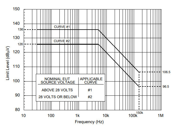
FIGURE CS101-2. CS101 power limit for all applications
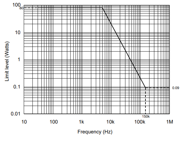
FIGURE CS101-3. Calibration.
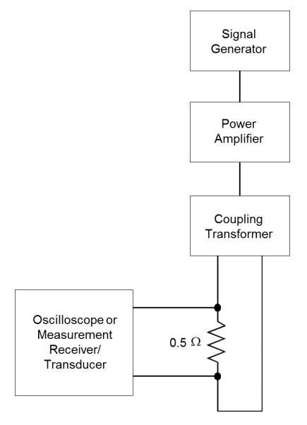
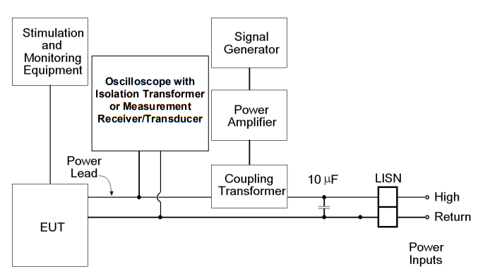
FIGURE CS101-4. Signal injection, DC or single phase AC.
_20.png)
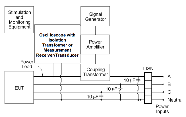
FIGURE CS101-5. Signal injection, 3-phase wye.
_20.png)
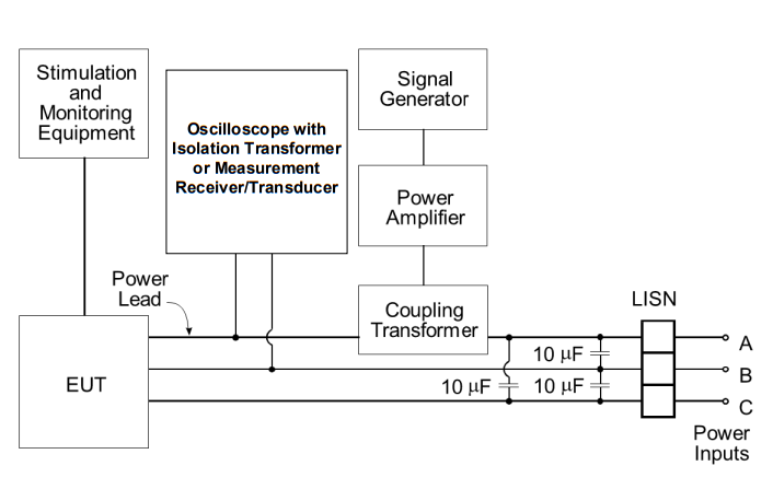
FIGURE CS101-6. Signal injection, 3-phase delta
_20.png)
Download Standard
This test procedure is used to verify the ability of the EUT to withstand signals coupled onto input power leads. There are two methods provided for making measurements of the applied signal. The first uses an oscilloscope with a power input isolation transformer. The second uses a measurement receiver together with a transducer. The transducer electrically isolates the receiver from the EUT power and reduces the levels to protect the receiver.
Test Equipment
The test equipment shall be as follows:- Signal generator
- Power amplifier
- Oscilloscope or measurement receiver
- Coupling transformer
- Capacitor, 10 μF
- Isolation transformer for oscilloscope use or transducer for measurement receiver use
- Resistor, 0.5 ohm
- LISNs
Procedures
The test procedures shall be as follows:- a. Turn on the measurement equipment and allow sufficient time for stabilization.
- b. Calibration.
- (1) Set the signal generator to the lowest test frequency.
- (2) Increase the applied signal until the oscilloscope or measurement receiver indicates the voltage level corresponding to the maximum required power level specified for the limit on Figure CS101-2. Verify the output waveform is sinusoidal for oscilloscope measurements.
- (3) Record the setting of the signal source.
- (4) Scan the required frequency range for testing and record the signal source setting needed to maintain the required power level.
- c. EUT testing.
- (1) Turn on the EUT and allow sufficient time for stabilization. CAUTION: Exercise care when performing this test since the "safety ground" of the oscilloscope is disconnected due to the isolation transformer and a shock hazard may be present.
- (2) Set the signal generator to the lowest test frequency. Increase the signal level until the required voltage or power level is reached on the power lead. (NOTE: Power is limited to the level calibrated in 5.7.3.4b(2).)
- (3) While maintaining at least the required signal level, scan through the required frequency range at a rate no greater than specified in Table III.
- (4) Susceptibility evaluation. (a) Monitor the EUT for degradation of performance. (b) If susceptibility is noted, determine the threshold level in accordance with 4.3.10.4.3.
- (5) Repeat 5.7.3.4c(2) through 5.7.3.4c(4) for each power lead, as required.
Test Setup
The test setup shall be as follows:- a. Maintain a basic test setup for the EUT as shown and described in Figures 2 through 5 and 4.3.8.
- b. Calibration. Configure the test equipment in accordance with Figure CS101-3. Set up the oscilloscope or measurement receiver/transducer to monitor the voltage across the 0.5 ohm resistor.
- c. EUT testing.
- (1) For DC or single-phase AC power, configure the test equipment as shown in Figure CS101-4.
- (2) For three-phase wye power (four power leads), configure the test setup as shown in Figure CS101-5.
- (3) For three-phase delta power, configure the test setup as shown in Figure CS101-6.
FIGURE CS101-1. CS101 voltage limit for all applications.

FIGURE CS101-2. CS101 power limit for all applications

FIGURE CS101-3. Calibration.

FIGURE CS101-4. Signal injection, DC or single phase AC.
_20.png)
FIGURE CS101-5. Signal injection, 3-phase wye.
_20.png)
FIGURE CS101-6. Signal injection, 3-phase delta
_20.png)
Download Standard
Products Used in Testing

AE Techron 3110 Standards Waveform Generator
- DC-20kHz (DAC), DC-300kHz (Sine)
- 120VAC, 1.0VA service, 1Ø
- IEC 6100-4-16, ISO 7637, ISO 16750-2


AE Techron 7228 Linear Power Amplifier
- Frequency Range: DC – 1MHz
- AC Power: 1000W RMS
- Slew rate: 100 V/μs


AE Techron T2000 Low-Frequency Conducted Susceptibility Transformer
- Frequency response: 10 Hz to 250 kHz.
- Turns ratio: 2:1 step down
- Audio power: 200W


Pearson Electronics PRD-240 Powerline Ripple Detector
- 10 Hz – 150 kHz
- 240 V AC / 270 V DC
- CS101 profile above 5 kHz
