
MIL
MIL-STD-461G RE102: Radiated Emissions, Electric Field
Standard Overview
MIL-STD-461G RE102 is applicable for radiated emissions from equipment and subsystem enclosures, and all interconnecting cables. For equipment with permanently mounted antennas, MIL-STD-461G RE102 does not apply at the transmitter fundamental frequency and the necessary occupied bandwidth of the signal. The requirement is applicable as follows:
MIL-STD-461G RE102 is used to verify that electric field emissions from the EUT and its associated cabling do not exceed specified requirements.
FIGURE RE102-1. RE102 limit for surface ship applications.
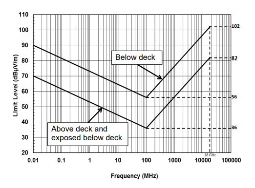
FIGURE RE102-2. RE102 limit for submarine applications.
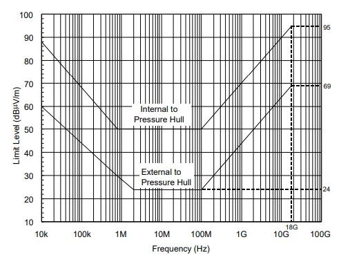
FIGURE RE102-3. RE102 limit for aircraft and space system applications.
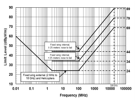
FIGURE RE102-4. RE102 limit for ground applications.
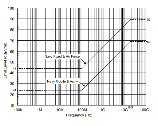
FIGURE RE102-5. Basic test setup.
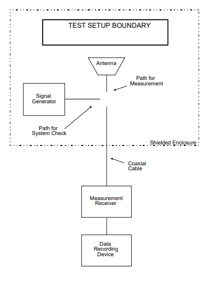
FIGURE RE102-6. Antenna positioning.
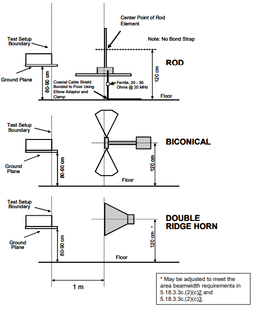
FIGURE RE102-7. Multiple antenna positions.
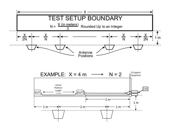
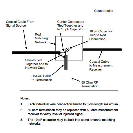
FIGURE RE102-8. Rod antenna system check.
Download Standard
| Ground | 2 MHz to 18 GHz |
| Ships, surface | 10 kHz to 18 GHz |
| Submarines | 10 kHz to 18 GHz |
| Aircraft (Army and Navy) | 10 kHz to 18 GHz |
| Aircraft (Air Force) | 2 MHz to 18 GHz |
| Space | 10 kHz to 18 GHz |
MIL-STD-461G RE102 is used to verify that electric field emissions from the EUT and its associated cabling do not exceed specified requirements.
Test Equipment
The test equipment shall be as follows:- a. Measurement receivers.
- b. Data recording device.
- c. Antennas:
- (1) 10 kHz to 30 MHz, 104 cm rod with impedance matching network. The signal output connector shall be bonded to the antenna matching network case.
- (a) When the impedance matching network includes a preamplifier (active rod), observe the overload precautions in 4.3.7.3.
- (b) Use a square counterpoise measuring at least 60 cm on a side.
- (2) 30 MHz to 200 MHz, Biconical, 137 cm tip to tip.
- (3) 200 MHz to 1 GHz, Double ridge horn, 69.0 by 94.5 cm opening.
- (4) 1 GHz to 18 GHz, Double ridge horn, 24.2 by 13.6 cm opening. d. Signal generators. e. Stub radiator. f. Capacitor, 10 pF. g. LISNs.
- (1) 10 kHz to 30 MHz, 104 cm rod with impedance matching network. The signal output connector shall be bonded to the antenna matching network case.
Procedures
The test procedures shall be as follows:
- a. Verify that the ambient requirements specified in 4.3.4 are met. Take plots of the ambient when required by the referenced paragraph.
- b. Turn on the measurement equipment and allow a sufficient time for stabilization.
- c. Using the system check path of Figure RE102-5, perform the following evaluation of the overall measurement system from the coaxial cable end used at each antenna to the data output device at 10.5 kHz (only for measurements implemented between 10 kHz and 2 MHz), 2.1 MHz, 12 MHz and 29.5 MHz for active rod antennas, 197 MHz for the biconical antenna, 990 MHz for the large double ridge horn and 17.5 GHz for the small double ridge horn. For rod antennas that use passive matching networks, the evaluation shall be performed at the center frequency of each band. A check shall also be performed when the measurement path is changed for a particular antenna such as the coaxial cable, addition or removal of preamplifiers, or different ports used on the measurement receiver. System check path verification shall be performed near the upper end of the affected frequency band.
- (1) Apply a calibrated signal level, which is at least 6 dB below the limit (limit minus antenna factor), to the coaxial cable at the antenna connection point.
- (2) Scan the measurement receiver in the same manner as a normal data scan. Verify that the data recording device indicates a level within ±3 dB of the injected signal level.
- (3) For the 104 cm rod antenna, remove the rod element and apply the signal to the antenna matching network through a capacitor connected to the rod mount as shown in Figure RE102-8. The capacitor value is nominally 10 pF, but shall be per the manufacturer’s instruction. Commercial calibration jigs or injection networks shall not be used.
- (4) If readings are obtained which deviate by more than ±3 dB, locate the source of the error and correct the deficiency prior to proceeding with the testing.
- d. Using the measurement path of Figure RE102-5, perform the following evaluation for each antenna to demonstrate that there is electrical continuity through the antenna.
- (1) Visually inspect each antenna for physical damage. Radiate a signal using an antenna or stub radiator at the highest measurement frequency of each antenna.
- (2) Tune the measurement receiver to the frequency of the applied signal and verify that a received signal of appropriate amplitude is present. NOTE: This evaluation is intended to provide a coarse indication that the antenna is functioning properly. There is no requirement to accurately measure the signal level.
- e. Turn on the EUT and allow sufficient time for stabilization.
- f. Using the measurement path of Figure RE102-5, determine the radiated emissions from the EUT and its associated cabling.
- (1) Scan the measurement receiver for each applicable frequency range, using the bandwidths and minimum measurement times in Table II.
- (2) Above 30 MHz, orient the antennas for both horizontally and vertically polarized fields.
- (3) Take measurements for each antenna position determined under 5.18.3.3c(2)(c).
Test SetUp
The test setup shall be as follows:- a. Maintain a basic test setup for the EUT as shown and described on Figures 1 through 5 and in 4.3.8. Ensure that the EUT is oriented such that the surface that produces the maximum radiated emissions is toward the front edge of the test setup boundary.
- b. Measurement system integrity check. Configure the test equipment as shown in Figure RE102-5.
- c. EUT testing.
- (1) For rod antenna measurements, the electrical bonding of the counterpoise is prohibited. The required configuration is shown in Figure RE102-6. The shield of the coaxial cable from the rod antenna matching network shall be electrically bonded to the floor in a length as short as possible (not to exceed 10 cm excess length). A ferrite sleeve with 20 to 30 ohms impedance (lossy with minimal inductance) at 20 MHz shall be placed near the center of the coaxial cable length between the antenna matching network and the floor.
- (2) Antenna positioning.
- (a) Determine the test setup boundary of the EUT and associated cabling for use in the positioning of antennas.
- (b) Use the physical reference points on the antennas shown in Figure RE102- 6 for measuring heights of the antennas and distances of the antennas from the test setup boundary.
- 1. Position antennas 1 meter from the front edge of the test setup boundary for all setups.
- 2. Position antennas 120 cm above the floor ground plane. For freestanding EUTs, antenna heights shall be determined as described in 5.18.3.3c(2)(c)2 and 5.18.3.3c(2)(c)3.
- 3. Ensure that no part of any antenna is closer than 1 meter from the walls and 0.5 meters from the ceiling and floor of the shielded enclosure.
- (c) The number of required antenna positions depends on the size of the test setup boundary and the number of enclosures included in the setup.
- 1. For testing below 200 MHz, use the following criteria to determine the individual antenna positions.
- a. For setups with the side edges of the boundary 3 meters or less, one position is required and the antenna shall be centered with respect to the side edges of the boundary.
- b. For setups with the side edges of the boundary greater than 3 meters, use multiple antenna positions at spacings as shown in Figure RE102-7. Determine the number of antenna positions (N) by dividing the edge-to-edge boundary distance (in meters) by 3 and rounding up to an integer.
- 2. For testing from 200 MHz up to 1 GHz, place the antenna in a sufficient number of positions such that the entire area of each EUT enclosure and the first 35 cm of cables and leads interfacing with the EUT enclosure are within the 3 dB beamwidth of the antenna.
- 3. For testing at 1 GHz and above, place the antenna in a sufficient number of positions such that the entire area of each EUT enclosure and the first 7 cm of cables and leads interfacing with the EUT enclosure are within the 3 dB beamwidth of the antenna.
- 1. For testing below 200 MHz, use the following criteria to determine the individual antenna positions.
FIGURE RE102-1. RE102 limit for surface ship applications.

FIGURE RE102-2. RE102 limit for submarine applications.

FIGURE RE102-3. RE102 limit for aircraft and space system applications.

FIGURE RE102-4. RE102 limit for ground applications.

FIGURE RE102-5. Basic test setup.

FIGURE RE102-6. Antenna positioning.

FIGURE RE102-7. Multiple antenna positions.

FIGURE RE102-8. Rod antenna system check.

Download Standard
Products Used in Testing

Keysight N9038A-526 | 3 Hz – 26.5 GHz
- Frequency: 10Hz - 26.5GHz
- AS/NZS CISPR 11, IEC/EN 61326-2-1
- Bandwidth: 200Hz - 1MHz (CISPR)

PMM 9010 | 10 Hz – 30 MHz
- Frequency: 10Hz - 30MHz
- CISPR 16-1-1, MIL-STD-461 RE103
- Bandwidth: 200 Hz - 1 MHz (CISPR)


PMM 9010F | 10 Hz – 30 MHz
- Frequency: 10Hz - 30MHz
- CISPR 14-1, MIL-STD-461
- Bandwidth: Up to 30MHz


Rohde & Schwarz ESW44 EMI Receiver
- Frequency: 1 Hz - 44 GHz
- MIL-STD-461 CE106, Ford FMC1278
- 1 Hz - 10 MHz (80 MHz option)
