
MIL
MIL-STD-461G RS101: Radiated Susceptibility, Magnetic Field
Standard Overview
MIL-STD-461G RS101 is applicable from 30 Hz to 100 kHz for equipment and subsystem enclosures, including electrical cable interfaces. The requirement is not applicable for electromagnetic coupling via antennas. For Army and Navy ground equipment, the requirement is applicable only to vehicles having a minesweeping or mine detection capability. For Navy ships and submarines, this requirement is applicable only to equipment and subsystems that have an operating frequency of 100 kHz or less and an operating sensitivity of 1 μV or better (such as 0.5 μV). For Navy aircraft, this requirement is applicable only to equipment installed on ASW capable aircraft, and external equipment on aircraft that are capable of being launched by electromagnetic launch systems.
This test procedure is used to verify the ability of the EUT to withstand radiated magnetic fields.
FIGURE RS101-1. RS101 limit for all Navy applications.
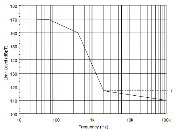
FIGURE RS101-2. RS101 limit for all Army applications.
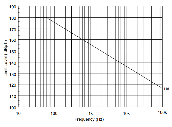
FIGURE RS101-3. Calibration of the radiating system.
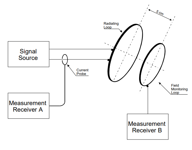
FIGURE RS101-4. Basic test setup.
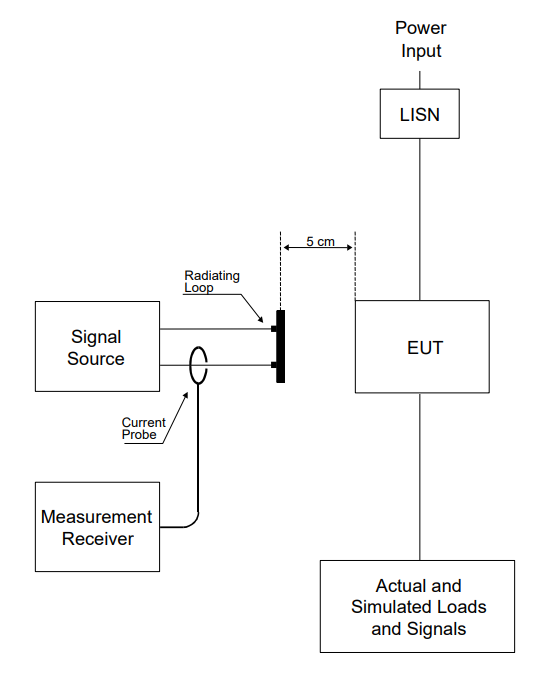
FIGURE RS101-5. Calibration of Helmholtz coils.
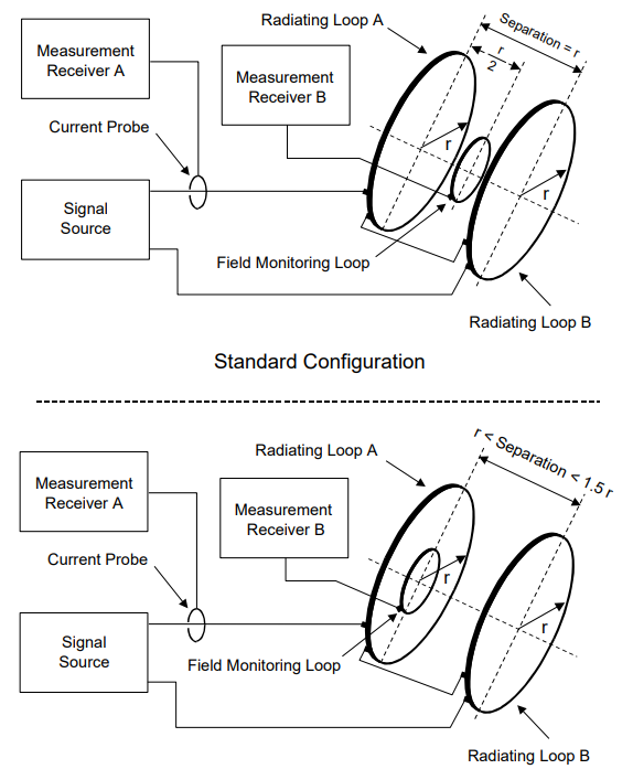
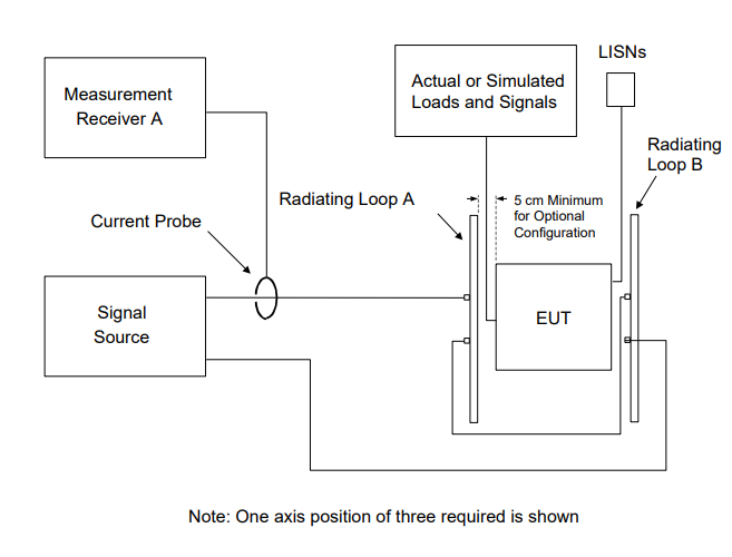
FIGURE RS101-6. Test setup for Helmholtz coils.
Download Standard
This test procedure is used to verify the ability of the EUT to withstand radiated magnetic fields.
Test Equipment
The test equipment shall be as follows:- Signal source
- Radiating loop having the following specifications:
- (1) Diameter: 12 cm
- (2) Number of turns: 20
- (3) Wire: No. 12 insulated copper
- (4) Magnetic flux density: 9.5x10⁷ pT/ampere of applied current at a distance of 5 cm from the plane of the loop.
- c. Loop sensor having the following specifications:
- (1) Diameter: 4 cm
- (2) Number of turns: 51
- (3) Wire: 7-41 Litz wire (7 Strand, No. 41 AWG)
- (4) Shielding: Electrostatic
- (5) Correction Factor: See manufacturer’s data for factors to convert measurement receiver readings to decibels above one picotesla (dBpT).
- d Measurement receiver or narrowband voltmeter
- e. Current probe
- f. LISNs
Procedures
The test procedures shall be as follows:- a. Turn on the measurement equipment and allow sufficient time for stabilization.
- b. Calibration.
- (1) Set the signal source to a frequency of 1 kHz and adjust the output to provide a magnetic flux density of 110 dB above one picotesla as determined by the reading obtained on measurement receiver A and the relationship given in 5.20.3.2b(4).
- (2) Measure the voltage output from the loop sensor using measurement receiver B.
- (3) Verify that the output on measurement receiver B is within ±3 dB of the expected value based on the antenna factor and record this value.
- c. EUT testing.
- (1) Turn on the EUT and allow sufficient time for stabilization.
- (2) Select test frequencies as follows:
- (a) Locate the loop sensor 5 cm from the EUT face or electrical interface connector being probed. Orient the plane of the loop sensor parallel to the EUT faces and parallel to the axis of connectors.
- (b) Supply the loop with sufficient current to produce magnetic field strengths at least 10 dB greater than the applicable limit but not to exceed 15 amps (183 dBpT).
- (c) Scan the applicable frequency range using the scan rates in Table III.
- (d) If susceptibility is noted, select no less than three test frequencies per octave at those frequencies where the maximum indications of susceptibility are present.
- (e) Reposition the loop successively to a location in each 30 by 30 cm area on each face of the EUT and at each electrical interface connector, and repeat 5.20.3.4c(2)(c) and 5.20.3.4c(2)(d) to determine locations and frequencies of susceptibility.
- (f) From the total frequency data where susceptibility was noted in 5.20.3.4c(2)(c) through 5.20.3.4c(2)(e), select three frequencies per octave over the applicable frequency range.
- (3) At each frequency determined in 5.20.3.4c(2)(f), apply a current to the radiating loop that corresponds to the applicable limit. Move the loop to search for possible locations of susceptibility with particular attention given to the locations determined in 5.20.3.4c(2)(e) while maintaining the loop 5 cm from the EUT surface or connector. Verify that susceptibility is not present.
Test Setup
The test setup shall be as follows:- a. Maintain a basic test setup for the EUT as shown and described on Figures 2 through 5 and 4.3.8.
- b. Calibration. Configure the measurement equipment, radiating loop, and loop sensor as shown in Figure RS101-3.
- c. EUT testing. Configure the test as shown in Figure RS101-4.
FIGURE RS101-1. RS101 limit for all Navy applications.

FIGURE RS101-2. RS101 limit for all Army applications.

FIGURE RS101-3. Calibration of the radiating system.

FIGURE RS101-4. Basic test setup.

FIGURE RS101-5. Calibration of Helmholtz coils.

FIGURE RS101-6. Test setup for Helmholtz coils.

Download Standard
Products Used in Testing

AE Techron 3110A Standards Waveform Generator
- DC-20kHz (DAC), DC-300kHz (Sine)
- 1Ø, 120VAC, 2A service
- RTCA/DO-160, MIL-STD-704


Solar Electronics 9229-1 Loop Sensor

Solar Electronics 9230-1 Radiating Loop | 30 Hz - 100 kHz
- Frequency range of 30 Hz to 100 KHz
- Radiating loop: 12 cm in diameter
- Sensing loop (used for calibration): 4 cm in diameter

PMM 9010F | 10 Hz – 30 MHz
- Frequency: 10Hz - 30MHz
- CISPR 14-1, MIL-STD-461
- Bandwidth: Up to 30MHz
