MIL
MIL-STD-461G CS116: Conducted Susceptibility, Damped Sinusoidal Transients, Cables and Power Leads
Standard Overview
MIL-STD-461G CS116 is used to verify the ability of the EUT to withstand damped sinusoidal transients coupled onto EUT associated cables and power leads. MIL-STD-461G CS116 applies to all interconnecting cables, including power cables, and individual high side power leads. Power returns and neutrals need not be tested individually. For submarine applications, MIL-STD-461G CS116 applies only to cables and leads that exit the pressure hull.
FIGURE CS116-1. Typical CS116 damped sinusoidal waveform.
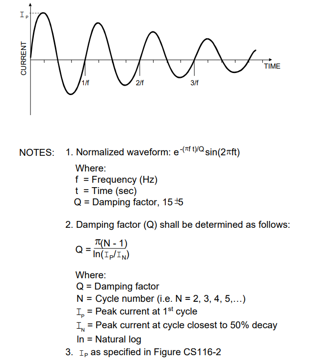
​FIGURE CS116-2. CS116 limit for all applications
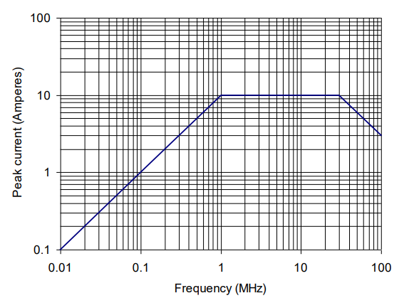
FIGURE CS116-3. Typical test setup for calibration of test waveform.
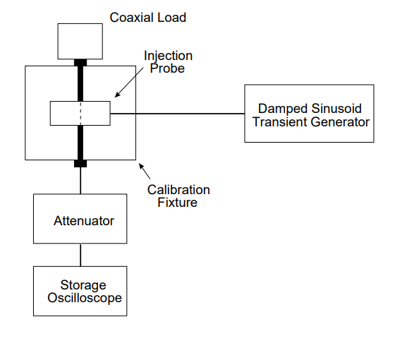
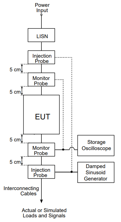
FIGURE CS116-4. Typical set up for bulk cable injection of damped sinusoidal transients.
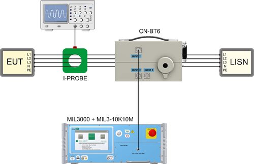
CS 116 test setup (10 kHz –10 MHz):
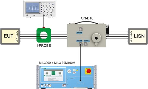
CS 116 calibration setup (30 MHz –100 MHz):
Test Equipment
- Damped sinusoid transient generator, ≤ 100 ohm output impedance
- Current injection probe
- Oscilloscope, 50 ohm input impedance
- Calibration fixture: Coaxial transmission line with 50 ohm characteristic impedance, coaxial connections on both ends, and space for an injection probe around the center conductor
- Current probe
- Waveform recording device
- Attenuators, 50 ohm
- Measurement receivers
- Coaxial loads, 50 ohm
- LISNs
Procedures
The test procedures shall be as follows:- a. Turn on the measurement equipment and allow sufficient time for stabilization.
- b. Calibration. Perform the following procedures using the calibration setup for waveform verification.
- (1) Set the frequency of the damped sine generator at 10 kHz.
- (2) Adjust the amplitude of the signal from the damped sine generator to the level specified in the requirement.
- (3) Record the damped sine generator settings.
- (4) Verify and record that the waveform complies with the requirements. Calculate and record the damping factor (Q).
- (5) Repeat 5.14.3.4b(2) through 5.14.3.4b(4) for each frequency specified in the requirement.
- c. EUT testing. Perform the following procedures, using the EUT test setup on each cable bundle interfacing with each connector on the EUT including complete power cables. Also, perform tests on each individual high side power lead (individual power returns and neutrals are not required to be tested). For delta configured power leads, test each power lead separately in addition to bulk cable.
- (1) Turn on the EUT and measurement equipment to allow sufficient time for stabilization.
- (2) Set the damped sine generator to a test frequency.
- (3) Apply the calibrated test signals to each cable or power lead of the EUT sequentially. Reduce the signal, if necessary, to produce the required current. For shielded cables or low impedance circuits, it may be preferable to increase the signal gradually to limit the current. Record the peak current obtained.
- (4) Monitor the EUT for degradation of performance.
- (5) If susceptibility is noted, determine the threshold level in accordance with 4.3.10.4.3.
- (6) Repeat 5.14.3.4c(2) through 5.14.3.4c(5) for each test frequency as specified in the requirement.
TEST Setup
- The test setup shall be as follows:
- a. Maintain a basic test setup for the EUT as shown and described in Figures 2 through 5 and 4.3.8.
- b. Calibration. Configure the test equipment in accordance with Figure CS116-3 for verification of the waveform.
- c. EUT testing:
- (1) Configure the test equipment as shown in Figure CS116-4.
- (2) To minimize errors, maintain the same signal circuit that was used for calibration between the attenuator at the calibration fixture (oscilloscope, coaxial cables, bulkhead connectors, additional attenuators, etc.) and connect the circuit to the monitor probe. Additional attenuation may be used, if necessary.
- (3) Place the injection and monitor probes around a cable bundle interfacing an EUT connector.
- (4) Locate the monitor probe 5 cm from the connector. If the overall length of the connector, backshell or backshell extension exceeds 5 cm, position the monitor probe as close to the connector's backshell or backshell extension as possible.
- (5) Position the injection probe 5 cm from the monitor probe.
FIGURE CS116-1. Typical CS116 damped sinusoidal waveform.
​FIGURE CS116-2. CS116 limit for all applications
FIGURE CS116-3. Typical test setup for calibration of test waveform.
FIGURE CS116-4. Typical set up for bulk cable injection of damped sinusoidal transients.
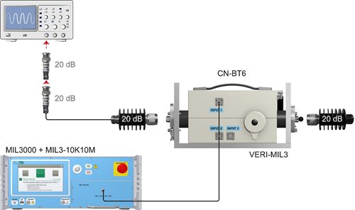
Calibration
CS 116 calibration setup (10 kHz –10 MHz):
CS 116 test setup (10 kHz –10 MHz):
CS 116 calibration setup (30 MHz –100 MHz):
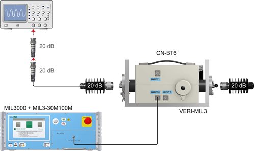
CS 116 test setup (30 MHz –100 MHz)​:
Products Used in Testing
Tektronix MDO4104C Mixed Domain Oscilloscope
- 4 analog channels
- 1 GHz, 500 MHz, 350 MHz, and 200 MHz bandwidth models
- Bandwidth is upgradeable (up to 1 GHz)
EMC Partner MIL3000 Military Test System
- Exceeds maximum test levels in MIL-STD-461
- One coupler for tests (CS115 & CS116)
- Test report data stored in MIL3000, accessible via USB or Ethernet
EMC Partner MIL3-10K10M Plugin for MIL3000 Test System
EMC Partner MIL3-30M100M Plugin for MIL3000 Test System
EMC Partner MIL-MG3 Military Test System
- Positive
- Negative
- Electronic Switching
Related MIL Standards
Explore All StandardsMIL-STD-1399-300: Interface Standard for Shipboard Systems
MIL-STD-1399-300 establishes electrical interface characteristics for shipboard equipment utilizing AC electric power to ensure compatibility between the user equipment and the electric power system. In MIL-STD-1399-300, characteristics of the electric power system are defined and tolerances are established, as well as requirements and test methods for ensuring compatibility of the shipboard user equipment with the power system. The policies and procedures established by MIL-STD-1399-300 are mandatory. This section and the basic standard are to be viewed as an integral single document for use in the design and testing of electric power systems and user equipment. This standard supersedes MIL-STD-1399-103.
Classification
In accordance with the MIL-STD-1399-300, the types of shipboard electric power to be supplied from the electric power system are classified as low voltage as follows:
Type I - Type I power is 440 or 115 volts (V), 60 hertz (Hz) ungrounded and is the standard shipboard electric power source. Type I power is used unless a deviation is granted
Type II - Type II power is 440 or 115 V, 400 Hz ungrounded and has only limited application. Use of Type II power requires the submittal and approval of a deviation request
Type III - Type III power is 440 or 115 V, 400 Hz ungrounded having tighter tolerances as compared to Type II. Type III power has restricted use and its use requires the submittal and approval of a deviation request
Special power classification for avionic shops and aircraft servicing
Types of shipboard electric power only for avionic shops and aircraft servicing are as follows:
Type I - Type I power is 115/200 V, 60 Hz, 3-phase, 4-wire, wye-grounded. This power is only provided for avionic shops.
Type III - Type III power is 115/200 V, 400 Hz, 3-phase, 4-wire, wye-grounded. This power is only provided for avionic shops and for aircraft servicing.
Special power classification for NATO load
MIL-STD-1576: Electroexplosive Subsystem Safety Requirements and Test Methods For Space Systems
MIL-STD-1576 establishes the general requirements and test methods for the design and development of electro-explosive subsystems to preclude hazards from unintentional initiation and from failure to fire. MIL-STD-1576 requirements apply to all subsystems utilizing electrically initiated explosive or pyrotechnic components. MIL-STD-1576 applies to all space vehicle systems (e.g., launch vehicles, upper stages, boosters, payloads, and related systems).
Download Standard
MIL-STD-188-125-2: HEMP Protection for Ground-Based C41 Facilities Performing Critical Missions...
MIL-STD-188-125-2 establishes minimum requirements and design objectives for high-altitude electromagnetic pulse (HEMP) hardening of transportable ground-based systems that perform critical, time-urgent command, control, communications, computer, and intelligence (C4I) missions.
MIL-STD-188-125-2 prescribes minimum performance requirements for low-risk protection from mission-aborting damage or upset due to HEMP threat environments defined in MIL-STD-2169. The standard also addresses minimum testing requirements for demonstrating that prescribed performance has been achieved and for verifying that the installed protection measures provide the operationally required HEMP hardness for the completed system. If the prescribed testing results in any hardware damage or functional upsets, the operational authority for the system will make the determination whether the observed event is mission aborting.
MIL-STD-188-125-2 defines the design and testing criteria for specifically designated transportable ground-based systems in HEMP-hardened, critical, time-urgent C4I networks. Such systems include subscriber terminals and data processing centers, transmitting and receiving communications stations, and relay systems. The standard applies to both new systems and modifications of existing systems. Although only local portions of system interconnects are addressed, it is assumed that survivable long-haul communications paths, fiberoptic links, or other hardened interconnects between systems will be provided as required for mission accomplishment.
Survivable C4I capabilities are essential to a credible military deterrent. This standard supports nuclear survivability objectives by providing a standardized, low-risk protection approach for transportable ground-based systems in HEMP-hardened C4I networks. These uniform requirements ensure balanced HEMP hardening for all critical systems and facilities in the
MIL-STD-461G CE101, CE102: Conducted Emissions, Audio Frequency Currents and Radio Frequency...
MIL-STD-461G CE101 and MIL-STD-461G CE102 are military test standards that pertain to audio frequency currents and radiofrequency potentials for conducted emissions testing, respectively.
MIL-STD-461G CE101
MIL-STD-461G CE101 applies from 30 Hz to 10 kHz for power leads, including returns, that obtain power from other sources not part of the EUT for surface ships, submarines, Army aircraft (including flight line) and Navy aircraft. For equipment intended to be installed on Navy aircraft, this requirement is applicable only if the platform contains Anti-Submarine Warfare (ASW) equipment, which operates between 30 Hz and 10 kHz, such as Acoustic (Sonobuoy) Receivers or Magnetic Anomaly Detectors (MAD). For AC applications, MIL-STD-461G CE101 is applicable starting at the second harmonic of the EUT power frequency. This test procedure is used to verify that electromagnetic emissions from the EUT do not exceed the specified requirements for power input leads including returns.
Test Equipment
The test equipment shall be as follows:
Measurement receivers
Current probes
Signal generator
Data recording device
Oscilloscope
Resistor (R)
LISNs
Procedures
The test procedures shall be as follows:
a. Turn on the measurement equipment and allow sufficient time for stabilization.
b. Measurement system integrity check. Evaluate the overall measurement system from the current probe to the data output device.
(1) Apply a calibrated signal level, which is at least 6 dB below the applicable limit at 1.1 kHz, 3 kHz, and 9.9 kHz, to the current probe.
(2) Verify the current level, using the oscilloscope and load resistor; also, verify that the current waveform is sinusoidal.
(3) Scan the measurement receiver for each frequency in the same manner as a normal data scan. Verify that the data recording device indicates a level within ±3 dB of the injected level.
(4) If readings are obtained which deviate by
MIL-STD-461G CE106: Conducted Emissions, Antenna Port
MIL-STD-461G CE106 is a military test standard procedure that applies to the antenna ports of transmitters, receivers, and amplifiers over the frequency range of 10 kHz to 40 GHz. The requirement does not apply to equipment designed with antennas permanently mounted to the EUT. The transmit mode portion of MIL-STD-461G CE106 is not applicable within the bandwidth of the EUT transmitted signal or within ±5 percent of the fundamental frequency, whichever is larger. For Navy shipboard applications with peak transmitter power greater than 1 kW, the 5% frequency exclusion will be increased by an additional 0.1% of the fundamental frequency for each dB above 1 kW of peak power.
Frequency Exclusion = ± f * (0.05 + (0.001/dB) * (PtPk [dBm] – 60 [dBm]))
Depending on the operating frequency range of the EUT, the start frequency of the test is as follows:
EUT Operating Frequency Range
Start Frequency of Test
10 kHz to 3 MHz
10 kHz
3 MHz to 300 MHz
100 kHz
300 MHz to 3 GHz
1 MHz
3 GHz to 40 GHz
10 MHz
The equipment will be tested to an upper-frequency limit based on the highest frequency generated or received by the EUT. For systems with the frequencies generated or received less than 1 GHz, the upper-frequency limit will be 20 times the highest frequency or 18 GHz, whichever is greater. For systems with frequencies generated or received greater than or equal to 1 GHz, the upper-frequency limit will be 10 times the highest frequency or 40 GHz, whichever is less. For equipment using waveguide, the requirement does not apply below eight-tenths of the waveguide's cutoff frequency. RE103 may be used as an alternative for MIL-STD-461G CE106 for testing transmitters with their operational antennas.
Test Equipment
Measurement receiver
Attenuators, 50 ohm
Rejection networks
Directional couplers
Dummy loads, 50 ohm
Signal
MIL-STD-461G CS101: Conducted Susceptibility, Power Leads
MIL-STD-461G CS101 applies from 30 Hz to 150 kHz for equipment and subsystem AC, limited to current draws ≤ 30 amperes per phase, and DC input power leads, not including returns. MIL-STD-461G CS101 is also applicable to systems that draw more than 30 amps if the system has an operating frequency of 150 kHz or less and an operating sensitivity of 1 μV or better (such as 0.5 μV). If the EUT is DC operated, MIL-STD-461G CS101 requirement applies over the frequency range of 30 Hz to 150 kHz. If the EUT is AC operated, this requirement applies to start from the second harmonic of the EUT power frequency and extending to 150 kHz.
This test procedure is used to verify the ability of the EUT to withstand signals coupled onto input power leads. There are two methods provided for making measurements of the applied signal. The first uses an oscilloscope with a power input isolation transformer. The second uses a measurement receiver together with a transducer. The transducer electrically isolates the receiver from the EUT power and reduces the levels to protect the receiver.
Test Equipment
The test equipment shall be as follows:
Signal generator
Power amplifier
Oscilloscope or measurement receiver
Coupling transformer
Capacitor, 10 μF
Isolation transformer for oscilloscope use or transducer for measurement receiver use
Resistor, 0.5 ohm
LISNs
Procedures
The test procedures shall be as follows:
a. Turn on the measurement equipment and allow sufficient time for stabilization.
b. Calibration.
(1) Set the signal generator to the lowest test frequency.
(2) Increase the applied signal until the oscilloscope or measurement receiver indicates the voltage level corresponding to the maximum required power level specified for the limit on Figure CS101-2. Verify the output waveform is sinusoidal for oscilloscope measurements.
(3) Record the setting of the signal source.
(4) Scan the required frequency
MIL-STD-461G CS103: Conducted Susceptibility, Antenna Port, Intermodulation
MIL-STD-461G CS103 is a receiver front-end susceptibility requirement applicable from 15 kHz to 10 GHz for equipment and subsystems, such as communications receivers, RF amplifiers, transceivers, radar receivers, acoustic receivers, and electronic warfare receivers as specified in the individual procurement specification.
MIL-STD-461G CS103 mandates that the EUT shall not exhibit any intermodulation products beyond specified tolerances when subjected to the limit requirement provided in the individual procurement specification.
This test procedure is used to determine the presence of intermodulation products that may be caused by undesired signals at the EUT antenna input ports.
Procedures
No test procedures are provided in the main body of this standard for this requirement. Because of the large variety of receiver designs being developed, the requirements for the specific operational characteristics of a receiver must be established before meaningful test procedures can be developed. Only general testing techniques are discussed in this appendix.
Intermodulation testing can be applied to a variety of receiving subsystems such as receivers, RF amplifiers, transceivers, and transponders.
Several receiver front-end characteristics must be known for proper testing for intermodulation responses. These characteristics generally should be determined by the conducted test. The maximum signal input that the receiver can tolerate without overload needs to be known to ensure that the test levels are reasonable and that the test truly is evaluating intermodulation effects. The bandpass characteristics of the receiver are important for determining frequencies near the receiver fundamental fo that will be excluded from the test. Requirements for this test are generally expressed in terms of a relative degree of rejection by specifying the difference in level between potentially interfering signals and the established sensitivity of the receiver
MIL-STD-461G CS104: Conducted Susceptibility, Antenna Port, Rejection of Undesired Signals
MIL-STD-461G CS104 is a receiver front-end susceptibility requirement applicable from 30 Hz to 20 GHz for equipment and subsystems, such as communications receivers, RF amplifiers, transceivers, radar receivers, acoustic receivers, and electronic warfare receivers as specified in the individual procurement specification. For Navy ships and submarines, MIL-STD-461G CS104 is applicable for all receivers. The applicable frequencies are a function of the front-end design of the unit being evaluated.
The EUT shall not exhibit any undesired response beyond specified tolerances when subjected to the limit requirement provided in the individual procurement specification.
MIL-STD-461G CS104 is used to determine the presence of spurious responses that may be caused by undesired signals at the EUT antenna input ports.
Procedures
No test procedures are provided in the main body of this standard for this requirement. Because of the large variety of receiver designs being developed, the requirements for the specific operational characteristics of a receiver must be established before meaningful test procedures can be developed. Only general testing techniques are discussed in this appendix.
Front-end rejection testing can be applied to a variety of receiving subsystems such as receivers, RF amplifiers, transceivers, and transponders.
Several receiver front-end characteristics must be known for proper testing. These characteristics generally should be determined by the test. The maximum signal input that the receiver can tolerate without overload needs to be known to ensure that the test levels are reasonable. The bandpass characteristics of the receiver are important for determining frequencies near the receiver fundamental that will be excluded from testing. Requirements for this test are often expressed in terms of a relative degree of rejection by specifying the difference in level between a potentially interfering signal and the established
MIL-STD-461G CS105: Conducted Susceptibility, Antenna Port, Cross-Modulation
MIL-STD-461G CS105 is a receiver front-end susceptibility requirement that applies from 30 Hz to 20 GHz only for receivers that normally process amplitude-modulated RF signals, as specified in the individual procurement specification.
According to MIL-STD-461G CS105, the EUT shall not exhibit any undesired response, due to cross modulation, beyond specified tolerances when subjected to the limit requirement provided in the individual procurement specification.
This test procedure is used to determine the presence of cross-modulation products that may be caused by undesired signals at the EUT antenna ports.
Procedures
No test procedures are provided in the main body of this standard for this requirement. Because of the large variety of receiver designs being developed, the requirements for the specific operational characteristics of a receiver must be established before meaningful test procedures can be developed. Only general testing techniques are discussed in this appendix.
Cross modulation testing should be applied only to receiving subsystems such as receivers, RF amplifiers, transceivers and transponders which extract information from the amplitude modulation of a carrier.
Several receiver front-end characteristics must be known for proper testing for cross modulation responses. These characteristics generally should be determined by test. The maximum signal input that the receiver can tolerate without overload needs to be known to ensure that the test levels are reasonable. The bandpass characteristics of the receiver are important for determining frequencies near the receiver fundamental that will be excluded from test. Requirements for this test are generally expressed in terms of a relative degree of rejection by specifying the difference in level between potentially interfering signals and the established sensitivity of the receiver under test. Therefore, determination of the sensitivity of the receiver is a key portion of
MIL-STD-461G CS106: Conducted Susceptibility, Transients, Power Leads
MIL-STD-461G CS106 is a military standard test procedure that is used to verify the ability of the EUT to resist transients coupled onto input power leads. The MIL-STD-461 CS106 establishes emission and susceptibility requirements to applicable submarine and surface ship equipment. Additionally, the MIL-STD-461 CS106 can be applied to subsystem AC and DC input power leads. The generator creates a transient pulse in the microsecond range and has repetitions of up to 15 pulses per second. The EUT will not show any signs of malfunction or change from set indications, beyond the tolerances indicated in the individual equipment or subsystem specification when subjected to a test signal with voltage levels as specified in Figure CS106-1, listed below. The 400-volt peak and 5-microsecond pulse is an accurate representation of transients observed on Navy platforms.
Test Equipment
Transient generator, ≤ 2 ohm source impedance
Oscilloscope
Differential probes
Isolation transformer
LISNs
Procedures
The test procedures shall be as follows:
a. Turn on the measurement equipment and allow sufficient time for stabilization.
b. Calibration
(1) Set the transient generator to minimum output
(2) Increase the applied signal until the oscilloscope indicates the voltage level corresponding to the limit. Verify the output waveform and pulse width
(3) Record the setting of the transient generator
c. EUT testing
(1) Turn on the EUT and allow sufficient time for stabilization. CAUTION: Exercise care when performing this test since the "safety ground" of the oscilloscope is disconnected due to the isolation transformer and a shock hazard may be present.
(2) Set the transient generator to minimum output.
MIL-STD-461G CS109: Conducted Susceptibility, Structure Current
MIL-STD-461G CS109 applies from 60 Hz to 100 kHz for equipment and subsystems that have an operating frequency of 100 kHz or less and an operating sensitivity of 1 μV or better (such as 0.5 μV). Handheld equipment is exempt from MIL-STD-461G CS109.
According to MIL-STD-461G CS109, the EUT shall not exhibit any malfunction, degradation of performance, or deviation from specified indications, beyond the tolerances indicated in the individual equipment or subsystem specification.
Test Equipment
The test equipment shall be as follows:
Signal generator
Amplifier (if required)
Isolation transformers
Current probe
Measurement receiver
Resistor, 0.5 ohm
Coupling transformer
Procedures
The test procedures shall be as follows:
a. Turn on the EUT and measurement equipment and allow sufficient time for stabilization.
b. Set the signal generator to the lowest required frequency. Adjust the signal generator to the required level as a minimum. Monitor the current with the current probe and measurement receiver.
c. Scan the signal generator over the required frequency range in accordance with Table III while maintaining the current level at least to the level specified in the applicable limit. Monitor the EUT for susceptibility.
d. If susceptibility is noted, determine the threshold level in accordance with 4.3.10.4.3.
e. Repeat 5.11.3.4b through 5.11.3.4d for each diagonal set of test points on each surface of the EUT to be tested.
Test Setup
The test setup shall be as follows:
a. It is not necessary to maintain the basic test setup for the EUT as shown and described in Figures 2 through 5 and in 4.3.8.
b. Calibration. No special calibration is required.
c. EUT testing.
(1) As shown in Figure CS109-2, configure the EUT and the test equipment (including the test signal source, the test current measurement equipment, and the equipment required for operating the EUT or measuring
MIL-STD-461G CS114: Conducted Susceptibility, Bulk Cable Injection
MIL-STD-461G CS114 applies from 10 kHz to 200 MHz for all interconnecting cables, including power cables. For EUTs intended to be installed on ships or submarines, an additional common mode limit of 77 dBμA applies from 4 kHz to 1 MHz on complete power cables (highs and returns - common mode test).
MIL-STD-461G CS114 does not apply to coaxial cables to antenna ports of antenna-connected receivers except for surface ships and submarines.
MIL-STD-461G CS114 is used to verify the ability of the EUT to withstand RF signals coupled onto EUT associated cabling.
Test Equipment
The test equipment shall be as follows:
Measurement receivers
Current injection probes (maximum and recommended minimum insertion loss shown in Figure CS114-2)
Current probes
Calibration fixture: coaxial transmission line with 50 ohm characteristic impedance, coaxial connections on both ends, and space for an injection probe around the center conductor.
Directional couplers
Signal generators
Plotter
Attenuators, 50 ohm
Coaxial loads, 50 ohm
Power amplifiers k. LISNs
Procedures
The test procedures shall be as follows:
a. Turn on the measurement equipment and allow sufficient time for stabilization.
b. Calibration. Perform the following procedures using the calibration setup.
(1) Set the signal generator to 10 kHz, unmodulated.
(2) Increase the applied signal until measurement receiver A indicates the current level specified in the applicable limit exists in the center conductor of the calibration fixture.
(3) Record the "forward power" to the injection probe indicated on measurement receiver B.
(4) Scan the frequency band from 10 kHz to 200 MHz and record the forward power needed to maintain the required current amplitude.
c. Verification. With the probes still in the calibration setup, configure the verification of the test system using Figure CS114-4. Conduct a scan as though this
MIL-STD-461G CS115: Conducted Susceptibility, Bulk Cable Injection, Impulse Excitation
MIL-STD-461G CS115 is used to verify the ability of the EUT to withstand impulse signals coupled onto EUT associated cabling. MIL-STD-461G CS115 applies to all aircraft, space, and ground-system interconnecting cables, including power cables. MIL-STD-461G CS115 is also applicable for surface ship and submarine subsystems and equipment when specified by the procuring activity.
Test Equipment
• Pulse generator, 50 ohm, charged line (coaxial)
• Current injection probe
• Drive cable, 50 ohm, 2 meters, 0.5 dB or less insertion loss at 500 MHz
• Current probe
• Calibration fixture: coaxial transmission line with 50 ohm characteristic impedance, coaxial connections on both ends, and space for an injection probe around the center conductor.
• Oscilloscope, 50 ohm input impedance
• Attenuators, 50 ohm
• Coaxial loads, 50 ohm
• LISNs
Procedures
The test procedures shall be as follows:
a. Turn on the measurement equipment and allow sufficient time for stabilization.
b. Calibration. Perform the following procedures using the calibration setup.
(1) Adjust the pulse generator source for the rise time, pulse width, and pulse repetition rate requirements specified in the requirement.
(2) Increase the signal applied to the calibration fixture until the oscilloscope indicates that the current level specified in the requirement exists in the center conductor of the calibration fixture.
(3) Verify that the rise time, fall time, and pulse width portions of the waveform have the correct durations and that the correct repetition rate is present. The precise pulse shape will not be reproduced due to the inductive coupling mechanism.
(4) Record the pulse generator amplitude setting.
c. EUT testing.
(1) Turn on the EUT and allow sufficient time for stabilization.
(2) Susceptibility evaluation.
(a) Adjust the pulse generator, as a minimum, for the amplitude setting
MIL-STD-461G CS117: Conducted Susceptibility, Lightning Induced Transients, Cables and Power Leads
MIL-STD-461G CS117 applies to all safety-critical equipment interconnecting cables, including complete power cables, and individual high side power leads. MIL-STD-461G CS117 is also applicable to non-safety critical equipment with interconnecting cables/electrical interfaces that are part of or connected to equipment performing safety-critical functions. It may apply to equipment performing non-safety critical functions when specified by the procuring activity. MIL-STD-461G CS117 also has limited applicability to surface ship equipment which have cables routed above deck.
Test Equipment
Lightning transient generator
Injection Transformers
Oscilloscope
Current monitor probes
Attenuators
Voltage Probe
LISNs
Procedures
The test procedures shall be as follows:
a. Turn on the measurement equipment and allow sufficient time for stabilization.
b. Calibration. Perform the following procedures using the calibration setup for waveform verification.
(1) Connect the transient generator to the primary input of the injection transformer.
(2) For each waveform, at the designated test level (VT or IT), record the voltage waveform with the calibration loop open or the current waveform with the calibration loop shorted, as applicable. Verify that each waveform complies with the relevant waveshape parameters shown in Figure CS117-1 through Figure CS117-6. The transient generator doesn't need to produce the associated voltage or current limit level (VL or IL) and waveshape. However, if the transient generator is capable of reaching the designated limit level (VL or IL), record and verify the limit waveform at that generator setting.
(3) For the Multiple Stroke and Multiple Burst tests, also verify the applicable pulse patterns and timing identified in Figure CS117-7 and Figure CS117-8.
(4) Reverse the transient generator polarity and repeat 5.15.3.4b(2) through 5.15.3.4b(3).
c. EUT testing.
(1) Turn on
MIL-STD-461G CS118: Personnel Borne Electrostatic Discharge (ESD)
MIL-STD-461G CS118 is the electrostatic discharge testing procedure for conducted susceptibility testing as specified by MIL-STD-461G. The ESD levels, test setup and test equipment of MIL-STD-461G CS118 are similar to IEC 61000-4-2 and RTCA/DO-160. To see the full version of MIL-STD-461G CS118, view MIL-STD-461G.
Advanced Test Equipment Rentals calibrates ESD guns in our lab
Recommended Bundle
For All 30kV Regulated Applications:
+
+
=
Teseq NSG 438
ESD Gun Simulator System
Teseq INA
Custom Discharge Network
Electro-Tech 949-2
Verification Kit
ESD Simulator Kit
Rent Bundle
CS118 Applicability
This requirement applies to electrical, electronic, and electromechanical subsystems and equipment that have a man-machine interface. It does not apply to equipment that interfaces with or controls ordnance items.
CS118 Limits
The EUT shall not exhibit any malfunction, degradation of performance, or deviation from specified indications, beyond the tolerances indicated in the individual equipment or subsystem specification when subjected to the values shown Table CS118-1. Contact up to 8kV is the required method. Air discharges shall be required only if specified by the procuring activity.
Purpose
This test procedure is used to verify the ability of the EUT to withstand personnel borne electrostatic discharge (ESD) in a powered-up configuration:
ESD Simulator Gun
LISN or other Isolation Transformer
GP: Ground Reference Plane (Aluminum or Sheet Metal)
HCP: Horizontal Plane (Aluminum or Sheet Metal)
VCP: Vertical Coupling Plane (Aluminum or Sheet Metal)
470 kOhm Resistor Cables to mount from HCP/VCP to GP
Insulation Material (Polyvinyl Chloride preferred material)
Get a quick overview with this demo
MIL-STD-1275: Characteristics of 28 Volt DC Input Power to Military Vehicles
MIL-STD-1275 is a military test standard that defines nominal 28 VDC voltage characteristics that are common to all military ground vehicles, specifically at the input power terminal of electronic/electrical assemblies that are directly connected to the distribution network in question. MIL-STD-1275 establishes a framework for similarity throughout military vehicle platforms. Design authorities are charged with making sure the 28 VDC applied to the input power terminal of the equipment meets MIL-STD-1275 requirements. This standard does not relate to power sources or power systems, but instead focuses on utilization equipment and required operating conditions.
General Requirements
Reverse Polarity
Utilization equipment is required to defend itself against damage caused by input power with reverse polarity; the magnitude of the reverse polarity input current should be equal to or less than the magnitude of the utilization equipment normal operating current, with reverse polarity voltage applied to the input power terminals of the utilization equipment.
Electromagnetic Compatibility
Utilization equipment should be compatible with relevant performance specification requirements for the mitigation of electromagnetic interference, electromagnetic pulses, power switching, and lightning-induced voltage spikes. (Electromagnetic interference is not covered by MIL-STD-1275).
Electrostatic Discharge
Utilization equipment must be compatible with applicable performance specification requirements for electrostatic discharge (ESD) immunity. (Electrostatic discharge is not covered by MIL-STD-1275).
Detailed Requirements
Voltage Compatibility Requirements
The first section of MIL-STD-1275's requirements, section 5.1, offers detailed requirements for the voltage conditions under which the device under test is intended to operate.
5.1.1 Steady-State Operation
Operating voltage range: between 20 VDC and
MIL-STD-1553: Aircraft Internal Time Division Command/Response Multiplex Data Bus
MIL-STD-1553 contains requirements for aircraft internal time division command/response multiplex data bus techniques which is utilized in systems integration of aircraft subsystems. Even with the use of this standard, subtle differences exist between multiplex data buses used on different aircraft due to particular aircraft mission requirements and the designer options allowed in this standard. The system designer must recognize this fact and design the multiplex bus controller hardware and software to accommodate such differences. These designer selected options must exist, so as to allow the necessary flexibility in the design of specific multiplex systems in order to provide for the control mechanism, architecture redundancy, degradation concept and traffic patterns peculiar to the specific aircraft mission requirements.
Scope:
This standard establishes requirements for digital, command/response, time division multiplexing (Data Bus) techniques on aircraft. It encompasses the data bus line and its interface electronics and also defines the concept of operation and information flow on the multiplex data bus and the electrical and functional formats to be employed.
Download Standard
MIL-STD-461
MIL-STD-461 is the military test standard that establishes requirements for the electromagnetic characteristics of equipment and systems designed for the US Department of Defense (DoD) activities and applicated by DoD personnel. In the pages of MIL-STD-461, a comprehensive set of test procedures are defined to fulfill the DoD’s electromagnetic emissions and susceptibility regulations. The procedures are divided into four families: conducted emissions (CE), radiated emissions (RE), conducted susceptibility (CS) and radiated susceptibility (RS). Each test procedure is named with an abbreviation followed by a code; for example, MIL-STD-461 CS116, which details conducted susceptibility tests necessary for damped sinusoidal transients, cables and power leads.
Detecting rogue signals and electromagnetic interference is crucial to the military, as everything from a cellphone to a navigation component on a stealth jet produces an electromagnetic field and can potentially threaten safety, efficiency or secret communications. In 1960, the DoD created an Electromagnetic Compatibility Program to respond to the growing trend of electromagnetic interference. The goal of the program was to integrate electromagnetic compatibility (EMC) into defense R&D. MIL-STD-461 was then jointly enacted by EMC personnel of the army, navy and air force, who addressed the interference reduction needs for the entire DoD in 1966 and produced the first version of MIL-STD-461 in 1967.
Ever since, the three branches of the military have collaborated to produce updated and expanded versions, cumulating in the most recent edition of the standard: MIL-STD-461G. The key differences between MIL-STD-461G and the previous version, MIL-STD-461F, can be seen in the chart below. Major changes in MIL-STD-461G include the removal of CS106 and the addition of CS117 and CS118.
Differences between MIL-STD-461F and
MIL-STD-461F: Electromagnetic Interference Characteristics of Equipment
MIL-STD-461F dictates the requirements for the electromagnetic compatibility (EMC) of devices and systems created for and used by the United States Department of Defense (DoD). MIL-STD-461F consists of an array of test procedures designed to help manufacturers and operators of electrical devices ensure the devices are not susceptible to electromagnetic interference (EMI) and do not create EMI themselves. The test procedures are broken up into four groups: radiated emissions (RE), conducted emissions (CE), radiated susceptibility (RS) and conducted susceptibility (CS). Procedures are named with one of the two-letter abbreviations followed by a code; for example, RE103, a radiation emissions test procedure specific to antenna spurious and harmonic outputs.
The EMC of military equipment is vital for the DoD; in military environments both at home and on the battlefield. Everything from smartphones to helicopter navigation systems produces an electromagnetic field and has the potential to compromise the safety, efficiency or secrecy of defense operations. The DoD created an Electromagnetic Compatibility Program in 1960 to address the growing concern that EMI was affecting military operations to integrate electromagnetic compatibility into defense industry R&D. The first version of MIL-STD-461 was then produced in 1967 by a joint committee of the three military branches to implement interference reduction throughout the entire DoD.
Since its inception, MIL-STD-461 has been revised and expanded by the collaborative efforts of the army, navy and air force, with the most recent edition being MIL-STD-461G. The changes made between MIL-STD-461F and MIL-STD-461G can be seen below. Major differences include the removal of CS106 and the addition of CS117 and CS118.
View MIL-STD-461G
Differences between MIL-STD-461F and
MIL-STD-461G: Electromagnetic Interference Characteristics of Equipment
MIL-STD-461G is the military test standard that establishes requirements for the electromagnetic compatibility (EMC) of devices and systems created for and used by the United States Department of Defense (DoD). In the pages of MIL-STD-461G, a comprehensive set of test procedures are defined to fulfill the DoD’s electromagnetic emissions and susceptibility regulations. The test procedures are broken up into four groups: radiated emissions (RE), conducted emissions (CE), radiated susceptibility (RS) and conducted susceptibility (CS). Procedures are named with one of the two-letter abbreviations followed by a code; for example, RE103, a radiation emissions test procedure specific to antenna spurious and harmonic outputs.
Detecting rogue signals and electromagnetic interference is crucial to the military, as everything from a cellphone to a navigation component on a stealth jet produces an electromagnetic field and can potentially threaten safety, efficiency or secret communications. The DoD created an Electromagnetic Compatibility Program to address the growing concern that EMI was affecting military operations with the goal of integrating electromagnetic compatibility into defense industry R&D. Ever since, the three branches of the military have collaborated to produce updated and expanded versions, culmunating in the most recent edition of the standard: MIL-STD-461G. The changes made between MIL-STD-461F and MIL-STD-461G can be seen below. Major differences include the removal of CS106 and the addition of CS117 and CS118.
View the differences between MIL-STD-461F and MIL-STD-461G.
Requirement Matrix
Equipment
CE101
CE102
CE106
CS101
CS103
CS104
CS105
CS109
CS114
Surface Ships
A
A
L
A
S
L
S
L
A
Submarines
A
A
L
A
S
L
S
L
A
Aircraft,
MIL-STD-464: RF Environmental Effects on Systems
MIL-STD-464 details the US military’s requirements for electromagnetic environmental effects on the interfaces of sea, space, ground and airborne systems. To safeguard the operation and performance of these systems, each should be compatible with equipment within the system and related subsystems. MIL-STD-464 primarily consists of design requirements and verification methods necessary to prevent or resolve these electromagnetic compatibility issues. Throughout the standard, Data Item Descriptions (DID) are referenced to determine problem areas early on in system design, minimize risks going forward and document testing results.
The current version of MIL-STD-464 is MIL-STD-464C.
The following are brief summaries of the standard's requirements:
5.1 Margins
Margins should be offered based on system performance requirements, tolerances and uncertainties.
5.2 Intra-system electromagnetic compatibility (EMC)
The system should be electromagnetically compatible with its own components.
5.3 External RF EME
The system should be electromagnetically compatible with a specified external electromagnetic environment to the extent that operational performance standards are met.
5.4 High-power microwave (HPM) sources
The system should meet its own requirements after exposure to narrowband and wideband HPM environments.
5.5 Lightning
The system should possess the appropriate resistance to both direct and indirect lightning effects.
5.6 Electromagnetic pulse (EMP)
The system should meet performance standards after exposure to the EMP environment.
5.7 Subsystems and equipment electromagnetic interference (EMI)
Individual components, equipment and subsystems must meet radiated immunity, radiated emissions, conducted immunity and conducted emissions test requirements.
5.8 Electrostatic charge control
The system should be able to both control and disperse electrostatic discharge (ESD) triggered
MIL-STD-704: Aircraft Electric Power Characteristics
MIL-STD-704 defines the requirements outlined by the Department of Defense for the characteristics of aircraft electric power generated at the input terminals of electric utilization equipment. MIL-STD-704 is intended to detail electric power quality requirements for DoD aircraft, but may also be used with commercial planes or other vehicle types. Standards like ISO 1540 and SAE-AS1212 also dictate aircraft electric power requirements, but are not generally relevant for military aircraft, as they do not address the areas of concern for military aircraft electric power quality and need wider limits compared to MIL-STD-704. MIL-STD-704 also takes into account legacy DoD equipment and aircraft electrical systems.
General Requirements
4.1 Aircraft Electric Power System Requirements
Aircraft electrical power systems should offer electric power with the characteristics specified in this standard at the utilization equipment terminals during all powerations of the power system.
Airframe manufacturers or modifiers are responsible for offering the distribution and protection network to the terminals of the utilization equipment while maintaining power characteristics specified in MIL-STD-704; characteristics of the power measured at the output terminal of an unregulated power source or the POR of a regulated power source should be within the limits specified in the detail specification applicable to the power source.
Protective devices should operate independently of control/regulation equipment.
4.2 Aircraft Utilization Equipment Requirements
Utilization equipment should be compatible with the power characteristics specified in MIL-STD-704.
Aircraft should operate at the performance level specified in its detail specification in all of the following modes of operation:
Normal
Abnormal
Transfer
Emergency
Starting
Loss of power or the loss of one or more phases of AC should not result in
MIL-STD-750: Test Methods for Semiconductor Devices
MIL-STD-750 defines testing methods for the environmental, physical and electrical testing of semiconductor devices utilized in military and aerospace electronic systems. The methods and procedures throughout the standard cover basic environmental, physical and electrical tests to assess resistance to deleterious effects of natural elements and conditions surrounding military and space operations. For this standard, the term "devices" includes such items as transistors, diodes, voltage regulators, rectifiers, tunnel diodes, and other related parts. This standard is intended to apply only to semiconductor devices.
The test methods and procedures described in the various parts of this multipart test method standard have been prepared to serve several purposes:
a. To specify suitable conditions obtainable in the laboratory that give test results equivalent to the actual service conditions existing in the field and to obtain reproducibility of the results of tests. The test methods described by this standard are not to be interpreted as an exact and conclusive representation of actual service operation in any one geographic location since it is known that the only true test for operation in a specific location is an actual service test at that point.
b. To describe, in a series of standards, all of the test methods of a similar character which now appear in the various joint-services semiconductor device specifications so that these test methods may be kept uniform and thus result in conservation of equipment, man-hours, and testing facilities. In achieving this objective, it is necessary to make each of the general test methods adaptable to a broad range of devices.
c. The test methods described by this standard for environmental, physical, and electrical testing of semiconductor devices shall also apply, when applicable, to parts not covered by an approved military sheet-form standard, specification sheet, or drawing.
Download Standard
MIL-STD-810G: Test Method Standard for Environmental Engineering Considerations and Laboratory Tests
MIL-STD 810G was developed for Department of Defense (DoD) applications and is often used for commercial products. The standard describes environmental management and engineering processes that can be of enormous value to generate confidence in the environmental worthiness and overall durability of a system design. The current version of the standard is MIL-STD 810G which incorporates the previous version (F) with corrections, changes and additions.
The purpose of this standard is to tailor a product’s “environmental design and test limits to the conditions that it will experience throughout its service life, and establishing laboratory test methods that replicate the effects of environments on material, rather than trying to reproduce the environments themselves.”
The MIL-STD 810G encompasses a series of tests approved by the department and agencies of the DoD. These tests address a range of environmental conditions such as temperature, humidity, vibration and acoustic noise. Advanced Test Equipment Rentals has equipment for testing almost every test method found in MIL-STD 810G.
Table of Contents
MIL-STD-810G, Method 501.5 - High Temperature
MIL-STD-810G, Method 502.5 - Low Temperature
MIL-STD-810G, Method 503.5 - Temperature Shock
MIL-STD-810G, Method 507.5 - Humidity
MIL-STD-810G, Method 520.3 - Temperature, Humidity, Vibration & Altitude
MIL-STD-810G, Method 501.5 - High Temperature
Purpose
Use high temperature tests to obtain data to help evaluate effects of high temperature conditions on materiel safety, integrity, and performance.
Application
Use this method to evaluate materiel likely to be deployed in areas where temperatures (ambient or induced) are higher than standard ambient.
Limitations
Limit use of this method to evaluating the effects of relatively
MIL-STD-883: Test Method Standard, Microcircuits
MIL-STD-883 establishes uniform methods, controls, and procedures for testing microelectronic devices suitable for use within Military and Aerospace electronic systems including basic environmental tests to determine resistance to deleterious effects of natural elements and conditions surrounding military and space operations; mechanical and electrical tests; workmanship and training procedures; and such other controls and constraints as have been deemed necessary to ensure a uniform level of quality and reliability suitable to the intended applications of those devices. For the purpose of this standard, the term "devices" includes such items as monolithic, multichip, film and hybrid microcircuits, microcircuit arrays, and the elements from which the circuits and arrays are formed. MIL-STD-883 is intended to apply only to microelectronic devices. The test methods, controls, and procedures described in MIL-STD-883 have been prepared to serve several purposes:
a. To specify suitable conditions obtainable in the laboratory and at the device level which give test results equivalent to the actual service conditions existing in the field, and to obtain reproducibility of the results of tests. The tests described herein are not to be interpreted as an exact and conclusive representation of actual service operation in any one geographic or outer space location. This is because it is known that the only true test for operation in a specific application and location is an actual service test under the same conditions.
b. To describe in one standard all of the test methods of a similar character which now appear in the various joint-services and NASA microelectronic device specifications, so that these methods may be kept uniform and thus result in conservation of equipment, many hours, and testing facilities. In achieving this objective, it is necessary to make each of the general tests adaptable to a broad range of devices.
c. To provide for a level
MIL-STD-461G RE101: Radiated Emissions, Magnetic Field
MIL-STD-461G RE101 is applicable from 30 Hz to 100 kHz for radiated emissions from equipment and subsystem enclosures, including electrical cable interfaces. The requirement does not apply to radiation from antennas. For Navy aircraft, this requirement is applicable only for aircraft with ASW equipment which operates between 30 Hz and 10 kHz such as Acoustic (Sonobuoy) Receivers or Magnetic Anomaly Detectors (MAD).
MIL-STD-461G RE101 is used to verify that the magnetic field emissions from the EUT and its associated electrical interfaces do not exceed specified requirements.
Test Equipment
The test equipment shall be as follows:
a. Measurement receivers
b. Data recording device
c. Loop sensor having the following specifications:
(1) Diameter: 13.3 cm
(2) Number of turns: 36
(3) Wire: DC resistance between 5 and 10 ohms
(4) Shielding: Electrostatic
(5) Correction factor: See manufacturer’s data for factors to convert measurement receiver readings to decibels above one picotesla (dBpT).
d. LISNs
e. Ohmmeter
f. Signal generator
Procedures
The test procedures shall be as follows:
a. Turn on the measurement equipment and allow sufficient time for stabilization.
b. Measurement system integrity check.
(1) Apply a calibrated signal level, which is at least 6 dB below the limit (limit minus the loop sensor correction factor), at a frequency of 50 kHz. Tune the measurement receiver to a center frequency of 50 kHz. Record the measured level.
(2) Verify that the measurement receiver indicates a level within ±3 dB of the injected signal level.
(3) If readings are obtained which deviate by more than ±3 dB, locate the source of the error and correct the deficiency prior to proceeding with the testing.
(4) Using an ohmmeter, verify that the resistance of the loop sensor winding is between 5 and 10 ohms.
c. EUT testing.
(1) Turn on the EUT and allow
MIL-STD-461G RE102: Radiated Emissions, Electric Field
MIL-STD-461G RE102 is applicable for radiated emissions from equipment and subsystem enclosures, and all interconnecting cables. For equipment with permanently mounted antennas, MIL-STD-461G RE102 does not apply at the transmitter fundamental frequency and the necessary occupied bandwidth of the signal. The requirement is applicable as follows:
Ground
2 MHz to 18 GHz
Ships, surface
10 kHz to 18 GHz
Submarines
10 kHz to 18 GHz
Aircraft (Army and Navy)
10 kHz to 18 GHz
Aircraft (Air Force)
2 MHz to 18 GHz
Space
10 kHz to 18 GHz
MIL-STD-461G RE102 is used to verify that electric field emissions from the EUT and its associated cabling do not exceed specified requirements.
Test Equipment
The test equipment shall be as follows:
a. Measurement receivers.
b. Data recording device.
c. Antennas:
(1) 10 kHz to 30 MHz, 104 cm rod with impedance matching network. The signal output connector shall be bonded to the antenna matching network case.
(a) When the impedance matching network includes a preamplifier (active rod), observe the overload precautions in 4.3.7.3.
(b) Use a square counterpoise measuring at least 60 cm on a side.
(2) 30 MHz to 200 MHz, Biconical, 137 cm tip to tip.
(3) 200 MHz to 1 GHz, Double ridge horn, 69.0 by 94.5 cm opening.
(4) 1 GHz to 18 GHz, Double ridge horn, 24.2 by 13.6 cm opening. d. Signal generators. e. Stub radiator. f. Capacitor, 10 pF. g. LISNs.
Procedures
The test procedures shall be as follows:
a. Verify that the ambient requirements specified in 4.3.4 are met. Take plots of the ambient when required by the referenced paragraph.
b. Turn on the measurement equipment and allow a sufficient time for stabilization.
c. Using the system check path of Figure RE102-5, perform the following evaluation of the overall measurement system from
MIL-STD-461G RE103: Radiated Emissions, Antenna Outputs
MIL-STD-461G RE103 may be used as an alternative for CE106 when testing transmitters with their intended antennas. This requirement is met if the emissions do not exceed the applicable RE102 limit in transmit mode. MIL-STD-461G RE103 is the preferred requirement unless the equipment or subsystem design characteristics preclude its use. RE103 should be the preferred method for systems using an active antenna or when the antenna impedance has a non-standard impedance curve. The requirement is applicable from 10 kHz to 40 GHz and not applicable within the bandwidth of the EUT transmitted signal or within ±5 percent of the fundamental frequency, whichever is larger. For Navy shipboard applications with peak transmitter power (PtPk) greater than 1 kW, the 5% frequency exclusion is increased by an additional 0.1% of the fundamental frequency for each dB above 1 kW of peak power.
Frequency Exclusion = ±f * (0.05 + (0.001/dB) * (PtPk [dBm] – 60 [dBm]))
Operating Frequency Range (EUT)
Start Frequency of Test
10 kHz to 3 MHz
10 kHz
3 MHz to 300 MHz
100 kHz
300 MHz to 3 GHz
1 MHz
3 GHz to 40 GHz
10 MHz
According to MIL-STD-461G RE103, the equipment will be tested to an upper-frequency limit based on the highest frequency generated or received by the EUT. For systems with the frequencies generated or received less than 1 GHz, the upper-frequency limit will be 20 times the highest frequency or 18 GHz whichever is greater. For systems with frequencies generated or received greater than or equal to 1 GHz, the upper-frequency limit will be 10 times the highest frequency or 40 GHz whichever is less. For equipment using waveguide, the requirement does not apply below eight-tenths of the waveguide's cutoff frequency.
This test procedure is used to verify that radiated spurious and harmonic emissions from transmitters do not exceed the specified
MIL-STD-461G RS101: Radiated Susceptibility, Magnetic Field
MIL-STD-461G RS101 is applicable from 30 Hz to 100 kHz for equipment and subsystem enclosures, including electrical cable interfaces. The requirement is not applicable for electromagnetic coupling via antennas. For Army and Navy ground equipment, the requirement is applicable only to vehicles having a minesweeping or mine detection capability. For Navy ships and submarines, this requirement is applicable only to equipment and subsystems that have an operating frequency of 100 kHz or less and an operating sensitivity of 1 μV or better (such as 0.5 μV). For Navy aircraft, this requirement is applicable only to equipment installed on ASW capable aircraft, and external equipment on aircraft that are capable of being launched by electromagnetic launch systems.
This test procedure is used to verify the ability of the EUT to withstand radiated magnetic fields.
Test Equipment
The test equipment shall be as follows:
Signal source
Radiating loop having the following specifications:
(1) Diameter: 12 cm
(2) Number of turns: 20
(3) Wire: No. 12 insulated copper
(4) Magnetic flux density: 9.5x10⁷ pT/ampere of applied current at a distance of 5 cm from the plane of the loop.
c. Loop sensor having the following specifications:
(1) Diameter: 4 cm
(2) Number of turns: 51
(3) Wire: 7-41 Litz wire (7 Strand, No. 41 AWG)
(4) Shielding: Electrostatic
(5) Correction Factor: See manufacturer’s data for factors to convert measurement receiver readings to decibels above one picotesla (dBpT).
d Measurement receiver or narrowband voltmeter
e. Current probe
f. LISNs
Procedures
The test procedures shall be as follows:
a. Turn on the measurement equipment and allow sufficient time for stabilization.
b. Calibration.
(1) Set the signal source to a frequency of 1 kHz and adjust the output to provide a magnetic flux density of 110 dB above one picotesla as determined by the reading
MIL-STD-461G RS103: Radiated Susceptibility, Electric Field
MIL-STD-461G RS103 is used to verify the ability of the EUT and associated cabling to withstand electric fields. MIL-STD-461G RS103 is applicable for equipment and subsystem enclosures and all interconnecting cables. MIL-STD-461G RS103 is applicable as follows:
Frequency Range
Applicability
2 MHz to 30 MHz
Army, Navy and optional for all others
30 MHz to 18 GHz
All
18 GHz to 40 GHz
Optional for all
Test Equipment
Signal Generator – Creates signals and modulations for the amplifier.
Power Amplifier – Takes signal, amplifies it sometimes greater than 1,000,000 times original power (0dbm going into 1000 W).
Low Loss Cables – Interconnect all coax equipment after the amplifier.
Dual Directional Coupler – Couples off-nominal values of forward and reverse power (typically by 40 dB or 50 dB).
Power Sensors – Measures coupled power from dual directional coupler for monitoring (may need attenuator between the forward coupled port and power sensor to avoid damage).
Power Meter – Dual channel, displays power sensor reading in dBm or Watts.
Tripod – Holds up the radiating antenna, non-metallic.
Radiating Antenna – Transducer which emits RF power into space from the signal source.
Electric Field Probe – Measures e-field strength (V/m) on X, Y, Z axes, and composite and returns data via fiber cable.
Fiber Optic Communication Link – Non-conductive communication link between field probe and probe interface.
Probe Interface – Provides both power and communication to the e-field probe.
Procedures
The test procedures shall be as follows:
a. Turn on the measurement equipment and EUT and allow sufficient time for stabilization.
b. Assess the test area for potential RF hazards and take necessary precautionary steps to assure the safety of test personnel.
c.
MIL-STD-461G RS105: Radiated Susceptibility, Transient Electromagnetic Field, or EMP...
MIL-STD-461G RS105 is a requirement applicable to equipment and subsystem enclosures located external to a shielded platform or facility. Therefore this test is intended solely for equipment being used on non-metallic platforms. MIL-STD-461G RS105 applies to Army aircraft for safety-critical equipment and subsystems located in an external installation.
The EUT shall not exhibit any malfunction, degradation of performance, or deviation from specified indications, beyond the tolerances indicated in the individual equipment or subsystem specification when subjected to an EMP waveform. At least five pulses shall be applied at the rate of not more than one pulse per minute.
There are a few variations of EMP to which MIL-STD-461G RS105 tests. Nuclear electromagnetic pulses (NEMP) are magnetic fields caused by nuclear explosions. A high altitude nuclear EMP (HEMP) is another specific test to be performed at higher amplitudes for applications such as aircraft subsystem and component development. Another form of EMP is a non-nuclear electromagnetic pulse (NNEMP), which includes EMPs that are manmade with the use of technology.
Test Equipment
The test equipment shall be as follows:
Transverse electromagnetic (TEM) cell, parallel plate transmission line or equivalent
Transient pulse generator, monopulse output, plus and minus polarity
Storage oscilloscope, 700 MHz, single-shot bandwidth (minimum), variable sampling rate up to 1 Giga sample per second (GSa/s)
Terminal protection devices e. High-voltage probe, 1 GHz bandwidth (minimum)
B-dot sensor probe
D-dot sensor probe
LISNs
Integrator, time constant ten times the overall pulse width
Procedures
The test procedures shall be as follows:
a. Turn on the measurement equipment and allow sufficient time for stabilization.
b. Calibration. Perform the following procedures using the calibration setup:
(1) Generate a pulse and adjust the pulse generator to produce a