MIL
MIL-STD-461G RE101: Radiated Emissions, Magnetic Field
Standard Overview
MIL-STD-461G RE101 is applicable from 30 Hz to 100 kHz for radiated emissions from equipment and subsystem enclosures, including electrical cable interfaces. The requirement does not apply to radiation from antennas. For Navy aircraft, this requirement is applicable only for aircraft with ASW equipment which operates between 30 Hz and 10 kHz such as Acoustic (Sonobuoy) Receivers or Magnetic Anomaly Detectors (MAD).
MIL-STD-461G RE101 is used to verify that the magnetic field emissions from the EUT and its associated electrical interfaces do not exceed specified requirements.
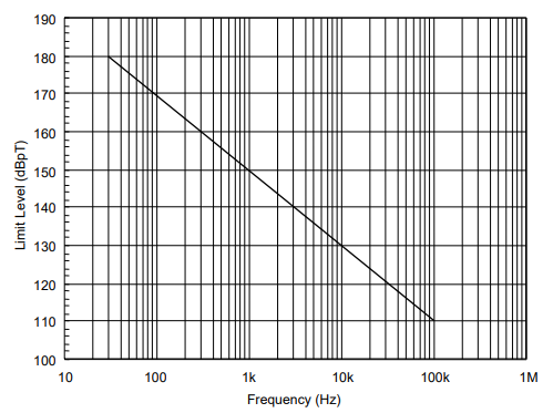
FIGURE RE101-1. RE101 limit for all Army applications.

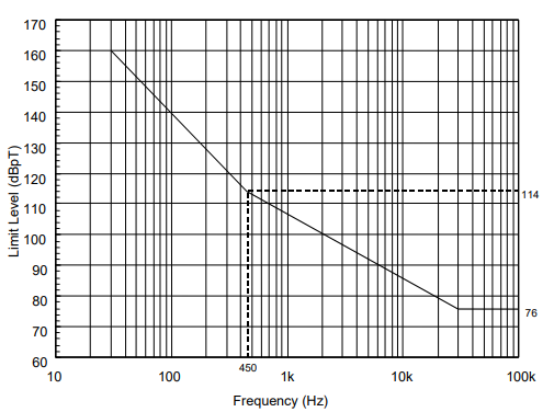
FIGURE RE101-2. RE101 limit for all Navy applications.

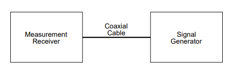
FIGURE RE101-3. Measurement system integrity check configuration.

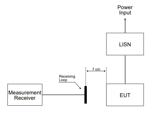
FIGURE RE101-4. Basic test setup.

Download Standard
MIL-STD-461G RE101 is used to verify that the magnetic field emissions from the EUT and its associated electrical interfaces do not exceed specified requirements.
Test Equipment
The test equipment shall be as follows:- a. Measurement receivers
- b. Data recording device
- c. Loop sensor having the following specifications:
- (1) Diameter: 13.3 cm
- (2) Number of turns: 36
- (3) Wire: DC resistance between 5 and 10 ohms
- (4) Shielding: Electrostatic
- (5) Correction factor: See manufacturer’s data for factors to convert measurement receiver readings to decibels above one picotesla (dBpT).
- d. LISNs
- e. Ohmmeter
- f. Signal generator
Procedures
The test procedures shall be as follows:- a. Turn on the measurement equipment and allow sufficient time for stabilization.
- b. Measurement system integrity check.
- (1) Apply a calibrated signal level, which is at least 6 dB below the limit (limit minus the loop sensor correction factor), at a frequency of 50 kHz. Tune the measurement receiver to a center frequency of 50 kHz. Record the measured level.
- (2) Verify that the measurement receiver indicates a level within ±3 dB of the injected signal level.
- (3) If readings are obtained which deviate by more than ±3 dB, locate the source of the error and correct the deficiency prior to proceeding with the testing.
- (4) Using an ohmmeter, verify that the resistance of the loop sensor winding is between 5 and 10 ohms.
- c. EUT testing.
- (1) Turn on the EUT and allow sufficient time for stabilization.
- (2) Locate the loop sensor 7 cm from the EUT face or electrical interface connector being probed. Orient the plane of the loop sensor parallel to the EUT faces and parallel to the axis of connectors.
- (3) Scan the measurement receiver over the applicable frequency range to locate the frequencies of maximum radiation, using the bandwidths and minimum measurement times of Table II.
- (4) Tune the measurement receiver to one of the frequencies or band of frequencies identified in 5.17.3.4c(3).
- (5) Monitor the output of the measurement receiver while moving the loop sensor (maintaining the 7 cm spacing) over the face of the EUT or around the connector. Note the point of maximum radiation for each frequency identified in 5.17.3.4c(4).
- (6) At 7 cm from the point of maximum radiation, orient the plane of the loop sensor to give a maximum reading on the measurement receiver and record the reading. If the measured emission exceeds the limit at the 7 cm distance, increase the measurement distance until the emission falls within the specified limit. Record the emissions and the measurement distance for assessment by the procuring activity
- NOTE: The EUT shall comply with the applicable RE101 limit at 7 cm.
- (7) Repeat 5.17.3.4c(4) through 5.17.3.4c(6) for at least two frequencies of maximum radiation per octave of frequencies below 200 Hz and for at least three frequencies of maximum radiation per octave above 200 Hz.
- (8) Repeat 5.17.3.4c(2) through 5.17.3.4c(7) for each face of the EUT and for each EUT electrical connector.
TEST SETUP
The test setup shall be as follows:- a. Maintain a basic test setup for the EUT as shown and described on Figures 2 through 5 and 4.3.8.
- b. Measurement system integrity check. Configure the measurement setup as shown in Figure RE101-3.
- c. EUT testing. Configure the measurement receiving loop and EUT as shown in Figure RE101-4.
FIGURE RE101-1. RE101 limit for all Army applications.

FIGURE RE101-2. RE101 limit for all Navy applications.

FIGURE RE101-3. Measurement system integrity check configuration.

FIGURE RE101-4. Basic test setup.

Download Standard
