


_17.png)

Advanced Amplifiers AA-2640G-40 Solid State Amplifier
- 26.5 - 40.0 GHz
- 40 W
- 46 dB min

Advanced Amplifiers AA-2640G-200 Solid State Power Amplifier
- 26.5 - 40.0 GHz
- 200 W
- 53 dB min
-compressed_25.png)
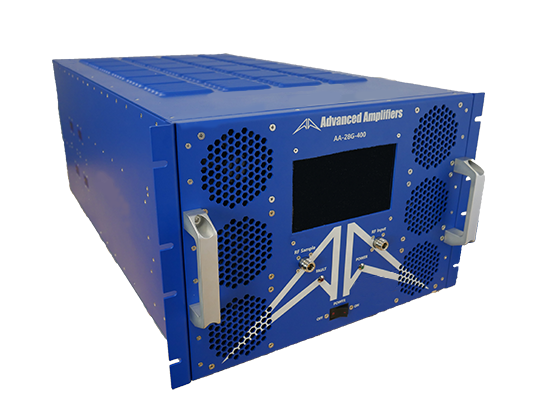
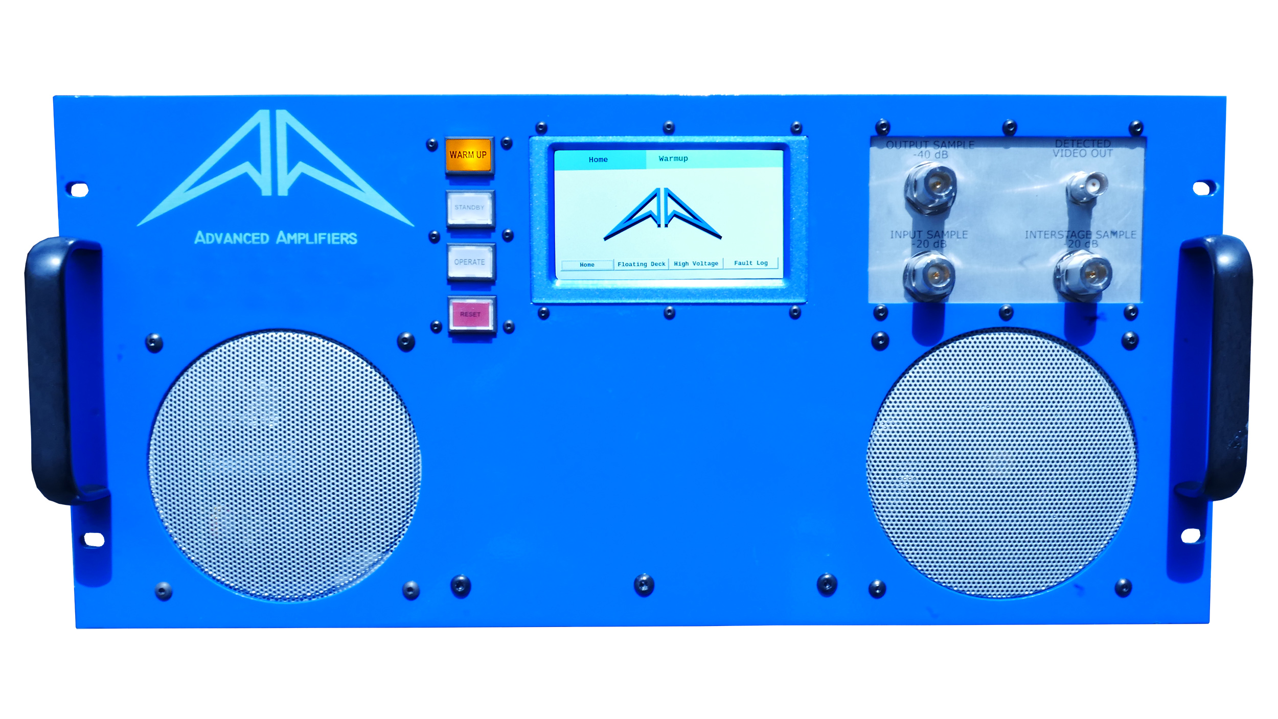
Advanced Amplifiers AA-28G-400 Solid State CW/Pulse Amplifier
- 2.0 - 8.0 GHz
- 400 W
- 56 dB min
Advanced Amplifiers AA-28G-500-GT TWT Pulse Amplifier
- 2.0 - 8.0 GHz
- 500 W
- 56 dB min

Advanced Amplifiers AA-618G-100 Solid State Amplifier
- 6.0 - 18.0 GHz
- 100 W
- 50 dB min
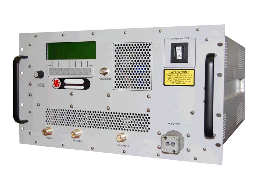
IFI T251-500A TWT Amplifier | 0.8 GHz – 2.5 GHz, 500 W
- Digital display monitors: collector current, collector voltage, helix current, helix voltage, forward rf power, reflected rf power, filament hours, beam hours
- Status indicators: power on, standby, RF on/operate
- Faults: helix overcurrent, VSWR overload, thermal overloads, air flow, collector overcurrent

Advanced Amplifiers AA-80M1G-300 Solid State Amplifier
- 80.0 MHz - 1.0 GHz
- 300 W
- 54 dB ± 2.0 dB min

Advanced Amplifiers AA-618G-40 Solid State Amplifier
- 6.0 - 18.0 GHz
- 40 W
- 46 dB min

Advanced Amplifiers AA-700M6G-50 Solid State Amplifier
- 0.7 - 6.0 GHz
- 50 W
- 47 dB min
-min_24.jpg "Advanced Amplifiers AA-13G-500")
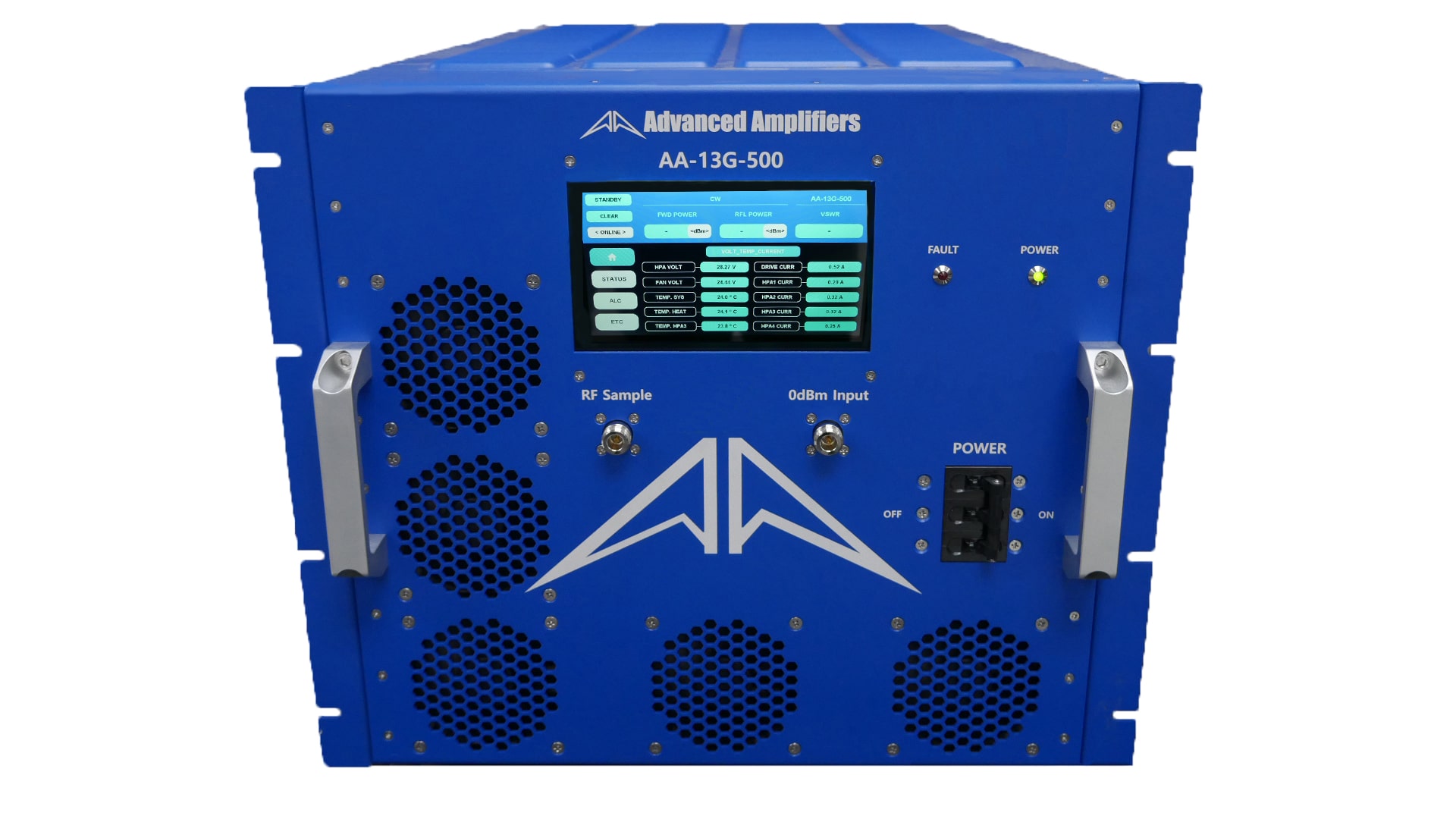
Advanced Amplifiers AA-13G-500 Solid State Amplifier
- 1.0 - 3.0 GHz
- 500 W
- 57 dB min
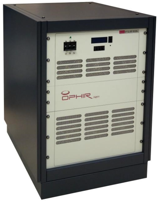
Ophir 5089 Linear Power RF Amplifier
- Solid-state broadband high-power RF amplifier
- 1000 Watt broadband amplifier
- Frequency range of 10 kHz - 200 MHz

Advanced Amplifiers AA-12G-2KWP Solid State Pulse Amplifier
- 1.0 - 2.0 GHz
- 2000 W
- 63 dB min

Advanced Amplifiers AA-1826G-40 Solid State Amplifier
- 18.0 - 26.5 GHz
- 40 W
- 46 dB min

Advanced Amplifiers AA-2100M-1000 Solid State Amplifier
- 2 - 100 MHz
- 1000 W
- 60 dB min

Empower 2170 Solid State Broadband High Power Amplifier 1 GHz - 3 GHz, 1000 W
- 1.0 - 3.0 GHz
- 1000 W
- 63 dB

-min_24.jpg "Advanced Amplifiers AA-13G-500/1KWP")
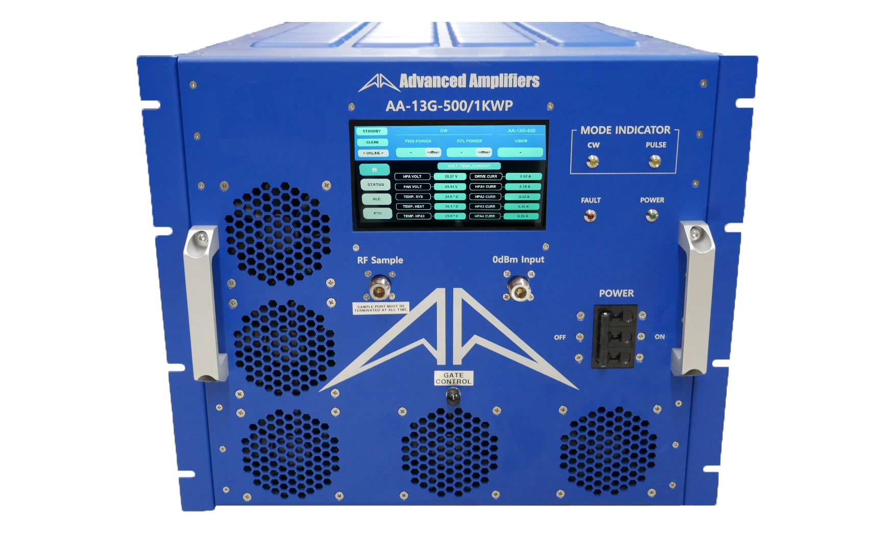
Advanced Amplifiers AA-13G-500/1KWP Solid State RF Amplifier
- Frequency Range: 0.8 - 3.2GHz
- Output: 1kW, 60dBm
- Duty Cycle: 10%, Pulse Width: up to 560μs

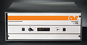
Amplifier Research 250S1G6
- 700 MHz- 6 GHz
- 250 W
- 54 dB

Amplifier Research 40S6G18-L Solid State CW Amplifier, 6 GHz - 18 GHz, 40 Watts
- 6.0 -18.0 GHz
- 40 W
- 46 dB min
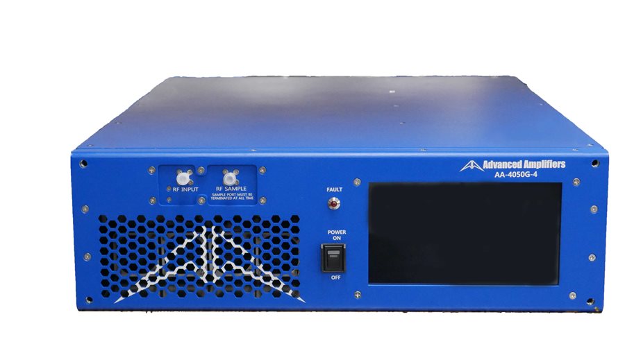
Advanced Amplifiers AA-4050G-4 Solid State Amplifier
- 40.0 - 50.0 GHz
- 4 W
- 36 dB min

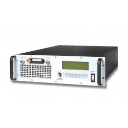
IFI S31-500-900P | Dual Mode CW/Pulse Amplifier
- 0.8 - 3.1 GHz
- 900 W
- 60 dB
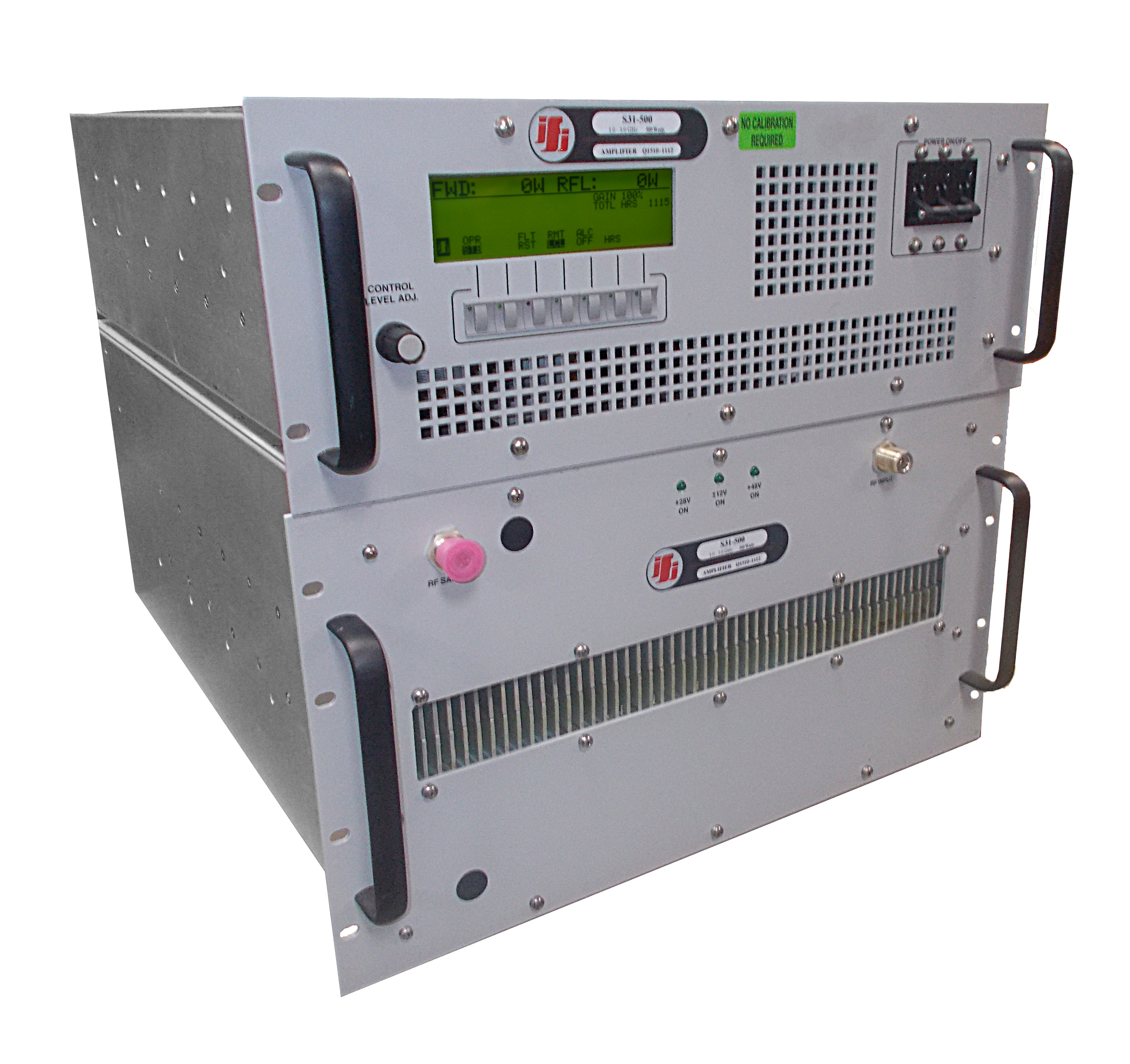
IFI S31-500 Solid State RF Power Amplifier 800 MHz - 3 GHz, 500 Watts
- VSWR Reflected Power Protection, the unit operates without damage or oscillation into any magnitude of phase or load impedance, Open and Short Circuit Protection.
- Alternate Prime Power (specify at time of order)
- GPIB IEEE 488 and RS232 Remote Control
_24.jpg)
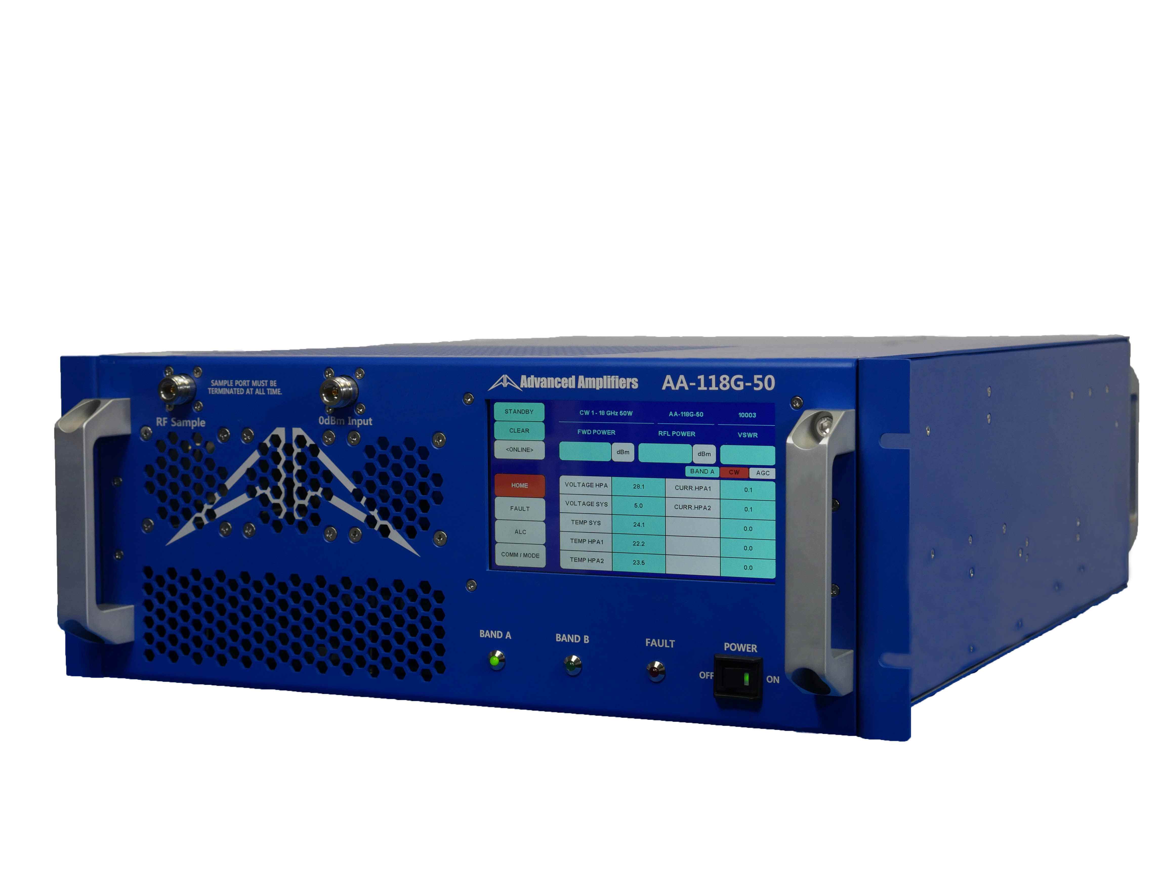
Advanced Amplifiers AA-118G-50 Solid-State High Power Amplifier
- 1.0 - 18.0 GHz
- 50 W
- 47 dB min
IFI T2618-40 Millimeter TWT Amplifier, 18 GHz - 26.5 GHz, 40 Watts
- 18 - 26.5 GHz
- 40 W
- 46 dB min

Advanced Amplifiers AA-618G-300-GT TWT High Power Amplifier
- 6.0 - 18.0 GHz
- 300 W
- 54 dB min
IFI SMCC500 Solid State Amplifier
- 200 - 1000 MHz
- 500 W
- 57 dB min