
Standard Overview
RTCA/DO-160 Section 20 provides test procedures to determine if equipment will operate when the EUT and its interconnecting cables are exposed to Radio Frequency interference. Continuous Wave (CW), Square Wave AM (SW), and Pulse Modulated (PM) RF signals are required. A Line Impedance Stabilization Network (LISN) must be inserted in series with each power lead and ungrounded power return lead, with a 10 uF capacitor connected between the power input of the LISN and the ground plane.
RTCA/DO-160 Section 20 has been updated to reflect the requirements of the new FAA rule for High Intensity Radiated Fields testing, also known as HIRF Testing, which is a form of EMC testing applicable to equipment that is subject to extreme electromagnetic environments and/or mission-critical equipment whose failure would be hazardous to human safety. HIRF requirements are applied to ensure that the aircraft electrical and electronic systems can continue safe operation without interruption, failure or malfunction.
During testing, the RF current induced into the cable or lead under test is monitored with a calibrated RF current probe, and the RF power applied to the injection probe is increased until the appropriate current level (as defined by the applicable Equipment Category used) is reached.
_20.png)
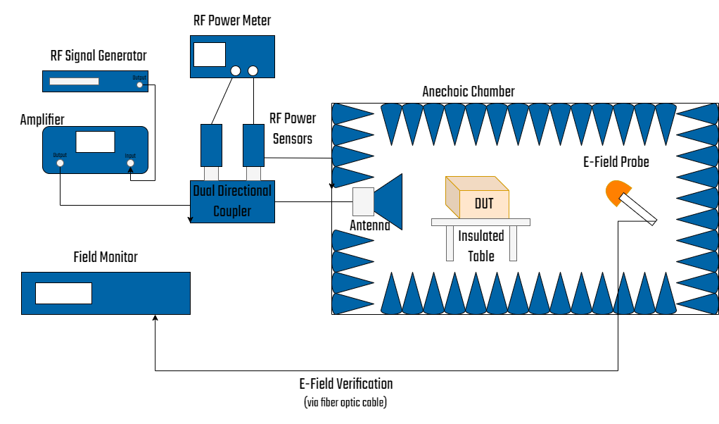
There two RF radiated susceptibility test methods specified in RTCA/DO-160 Section 20. The first method uses a standard semi-anechoic chamber as in MIL-STD-461F test method RS103 and requires the chamber to be lined with an RF absorber of a specified minimum performance. The minimum antenna distance is normally 1 meter, and multiple antenna positions are required when the beamwidth of the antenna does not completely cover the system. The RF power applied to the antenna input, that is required to achieve the specified test level, is recorded for each antenna used. During EUT testing, the calibrated power level for each test frequency is applied to the antenna.
The second method uses a Reverberation Chamber, which requires a Field Uniformity Validation and Maximum Chamber Loading Verification before the first use of the chamber, or after any modifications. Field Uniformity measurements are performed with a 3-axis E-Field probe at up to nine different positions within the chamber. Additionally, a passive, linear, monitor antenna is moved to different positions within the chamber to calibrate the monitor antenna for use before each test. This calibration allows the monitor antenna to be used to measure Chamber Q, Time Constant, and Test Level determination, during EUT testing.
The RF power level required to achieve the desired test level for each test frequency is determined by injecting a known RF power level (typically 1 watt) into the chamber, and then measuring the field level inside the Reverb Chamber with the monitor antenna, after the EUT installed in the chamber.
RTCA/DO-160 provides standard procedures and environmental test criteria for testing airborne equipment for the entire spectrum of aircraft from light, general aviation aircraft and helicopters through the "jumbo jets" and SST categories of aircraft. The tests outlined in this standard are performed to meet FAA and international regulations for electrical and electronic equipment installed on commercial aircraft.
RTCA/DO-160 G is the current version of this standard. Coordinated with EUROCAE, RTCA/DO-160G and EUROCAE/ED-14G are identically worded. DO-160G is recognized by the International Organization for Standardization (ISO) as de facto international standard ISO-7137.
RTCA/DO-160 Section 20 has been updated to reflect the requirements of the new FAA rule for High Intensity Radiated Fields testing, also known as HIRF Testing, which is a form of EMC testing applicable to equipment that is subject to extreme electromagnetic environments and/or mission-critical equipment whose failure would be hazardous to human safety. HIRF requirements are applied to ensure that the aircraft electrical and electronic systems can continue safe operation without interruption, failure or malfunction.
Conducted Susceptibility
Similar to MIL-STD-461F test method CS114, the RF conducted susceptibility test has the RF interference coupled into the EUT interconnecting cables and power leads using an injection probe calibrated (in a 50 ohm fixture) to the required test level before performing the test.During testing, the RF current induced into the cable or lead under test is monitored with a calibrated RF current probe, and the RF power applied to the injection probe is increased until the appropriate current level (as defined by the applicable Equipment Category used) is reached.
Radiated Susceptibility
Similar to MIL-STD-461F test method RS103, the EUT and its interconnecting cables and power leads are exposed to RF radiated fields in the frequency range of 100 MHz to 18 GHz.There two RF radiated susceptibility test methods specified in RTCA/DO-160 Section 20. The first method uses a standard semi-anechoic chamber as in MIL-STD-461F test method RS103 and requires the chamber to be lined with an RF absorber of a specified minimum performance. The minimum antenna distance is normally 1 meter, and multiple antenna positions are required when the beamwidth of the antenna does not completely cover the system. The RF power applied to the antenna input, that is required to achieve the specified test level, is recorded for each antenna used. During EUT testing, the calibrated power level for each test frequency is applied to the antenna.
The second method uses a Reverberation Chamber, which requires a Field Uniformity Validation and Maximum Chamber Loading Verification before the first use of the chamber, or after any modifications. Field Uniformity measurements are performed with a 3-axis E-Field probe at up to nine different positions within the chamber. Additionally, a passive, linear, monitor antenna is moved to different positions within the chamber to calibrate the monitor antenna for use before each test. This calibration allows the monitor antenna to be used to measure Chamber Q, Time Constant, and Test Level determination, during EUT testing.
The RF power level required to achieve the desired test level for each test frequency is determined by injecting a known RF power level (typically 1 watt) into the chamber, and then measuring the field level inside the Reverb Chamber with the monitor antenna, after the EUT installed in the chamber.
Equipment Categories
Equipment Category designation for Section 20 consists of two letters. Conducted susceptibility test levels are designated with the first category character and radiated susceptibility test levels with the second category character. There are 7 Equipment Categories for conducted susceptibility, and 10 Equipment Categories for radiated susceptibility. These categories indicate the severity level of the tests performed, and/or the type of modulation used.RTCA/DO-160 provides standard procedures and environmental test criteria for testing airborne equipment for the entire spectrum of aircraft from light, general aviation aircraft and helicopters through the "jumbo jets" and SST categories of aircraft. The tests outlined in this standard are performed to meet FAA and international regulations for electrical and electronic equipment installed on commercial aircraft.
RTCA/DO-160 G is the current version of this standard. Coordinated with EUROCAE, RTCA/DO-160G and EUROCAE/ED-14G are identically worded. DO-160G is recognized by the International Organization for Standardization (ISO) as de facto international standard ISO-7137.


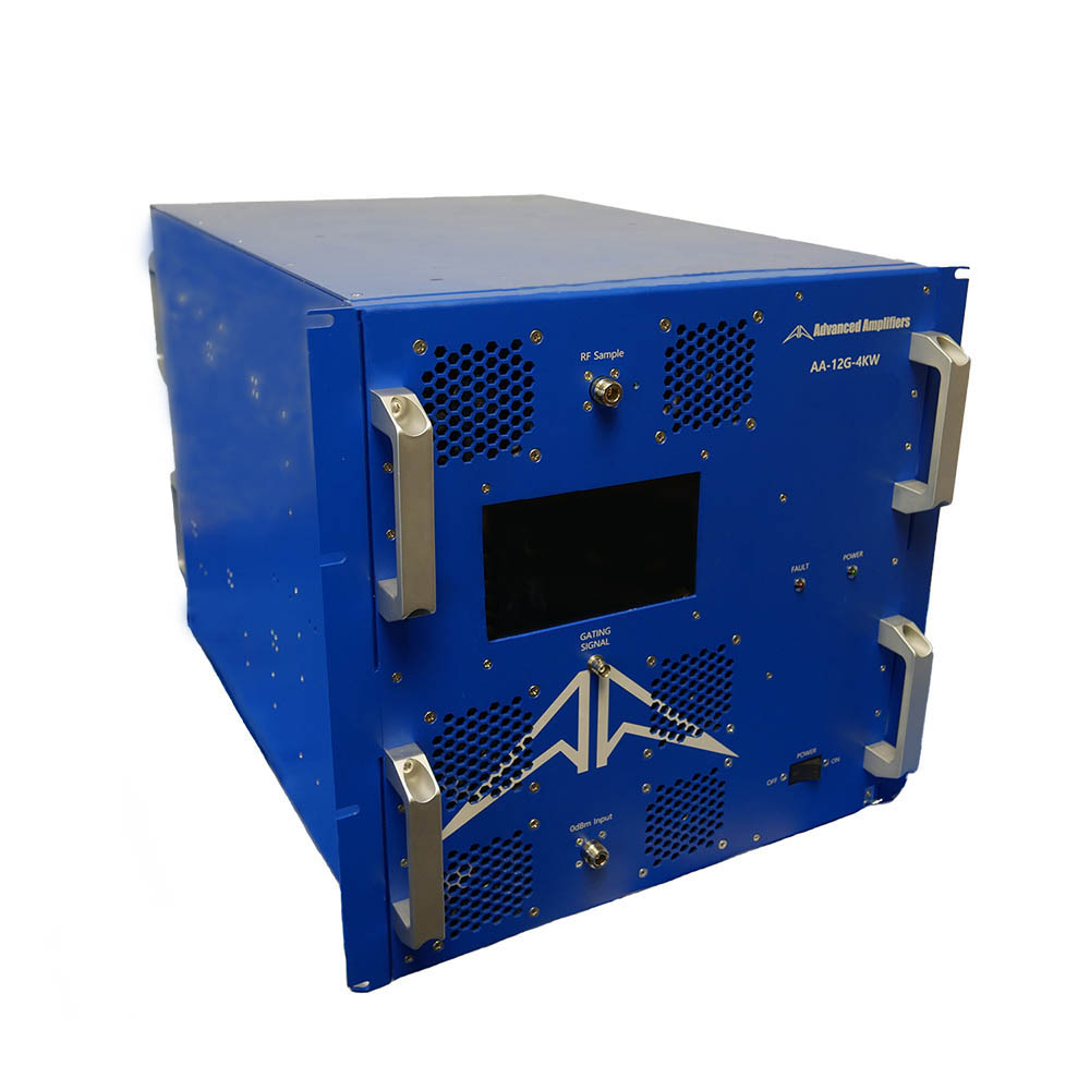-compressed_24.jpg?width=400 "Advanced Amplifiers AA-12G-4KWP")


