Standard Overview
MIL-STD-704 defines the requirements outlined by the Department of Defense for the characteristics of aircraft electric power generated at the input terminals of electric utilization equipment. MIL-STD-704 is intended to detail electric power quality requirements for DoD aircraft, but may also be used with commercial planes or other vehicle types. Standards like ISO 1540 and SAE-AS1212 also dictate aircraft electric power requirements, but are not generally relevant for military aircraft, as they do not address the areas of concern for military aircraft electric power quality and need wider limits compared to MIL-STD-704. MIL-STD-704 also takes into account legacy DoD equipment and aircraft electrical systems.

4.1 Aircraft Electric Power System Requirements
4.2 Aircraft Utilization Equipment Requirements
Figure 1
4.3 External Power Source Requirement
External electric power sources should offer power with characteristics specified in this standard at power input terminals of aircraft equipment. To allow for steady-state voltage drop, external power receptacle voltage should be as follows:
4.4 Test Requirements
Test method MIL-HDBK-704 should be used to determine that the utilization equipment complies with this standard. Aircraft should be tested to demonstrate the electric system's power characteristics and whether they are within the limits of the standard throughout all operating conditions of the aircraft and its utilization.
5.1 Transfer Operation Characteristics
Voltage and frequency should not vary between zero and normal operating limits for over 50 milliseconds, under conditions of bus or power source transfers, voltage, and frequency. Normal transients may occur upon transfer completion.
5.2 AC Power Characteristics
Figure 2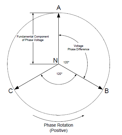
5.3 DC Power Characteristics
5.4 Load Characteristics
Download Standard
General Requirements
4.1 Aircraft Electric Power System Requirements
- Aircraft electrical power systems should offer electric power with the characteristics specified in this standard at the utilization equipment terminals during all powerations of the power system.
- Airframe manufacturers or modifiers are responsible for offering the distribution and protection network to the terminals of the utilization equipment while maintaining power characteristics specified in MIL-STD-704; characteristics of the power measured at the output terminal of an unregulated power source or the POR of a regulated power source should be within the limits specified in the detail specification applicable to the power source.
- Protective devices should operate independently of control/regulation equipment.
4.2 Aircraft Utilization Equipment Requirements
- Utilization equipment should be compatible with the power characteristics specified in MIL-STD-704.
- Aircraft should operate at the performance level specified in its detail specification in all of the following modes of operation:
- Normal
- Abnormal
- Transfer
- Emergency
- Starting
- Loss of power or the loss of one or more phases of AC should not result in equipment damage or unsafe conditions.
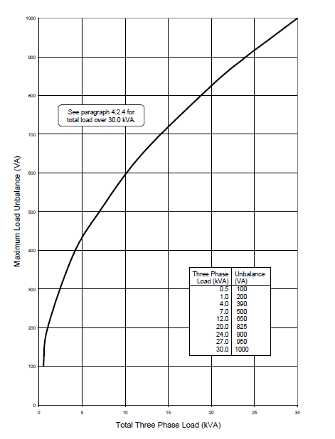
- Utilization equipment requiring over 0.5 kVA of AC power should be configured to use a three-phase steady-state balanced power. Load unbalance of individual utilization equipment should be within the limits displayed in Figure 1. It should be no greater than 3.33 percent of its total three-phase load if the total load is greater than 30 kVA. Single-phase AC power shall be used only on a line-to-neutral basis and AC power shall not be half-wave rectified.
Figure 1
4.3 External Power Source Requirement
External electric power sources should offer power with characteristics specified in this standard at power input terminals of aircraft equipment. To allow for steady-state voltage drop, external power receptacle voltage should be as follows:
| AC system | 28 VDC system | 270 VDC system |
| 113 to 118 volts | 24 to 29 volts | 260 to 280 volts |
| (AC voltage drop of 0 to 5 volts) | (DC voltage drop of 0 to 2 volts) | (DC voltage drop of 0 to 10 volts) |
4.4 Test Requirements
Test method MIL-HDBK-704 should be used to determine that the utilization equipment complies with this standard. Aircraft should be tested to demonstrate the electric system's power characteristics and whether they are within the limits of the standard throughout all operating conditions of the aircraft and its utilization.
Detailed Requirements
5.1 Transfer Operation Characteristics
Voltage and frequency should not vary between zero and normal operating limits for over 50 milliseconds, under conditions of bus or power source transfers, voltage, and frequency. Normal transients may occur upon transfer completion.
5.2 AC Power Characteristics
- Type System: AC systems should generate electrical power using single-phase or three-phase wire-connected grounded neutral systems.
- The voltage waveform should be a sine wave with a nominal voltage of 115/200 volts and a nominal frequency of 400 Hz.
- Variable frequency and double-voltage systems may be used as alternative electrical power systems; variable frequency systems and have frequencies varying from 360 to 800 Hz with a nominal voltage of 115/200 volts, while double-voltage systems have nominal voltages of 230/400 volts and a nominal frequency of 400 Hz.
- A third alternative for secondary electric power systems is single-phase 60 Hz systems.
- These systems have a nominal voltage of 115V with a nominal frequency of 60 Hz and are used only to support COTS equipment.
- Phase sequence: should be A-B-C, with wiring and terminals marked accordingly; generator terminals shall be marked T1-T2-T3 corresponding to A-B-C, respectively. The phase sequence shall be counterclockwise (positive) as shown in figure 2.
- For normal operating characteristics and abnormal operating characteristics, see the standard (emergency characteristics should be approached the same way as normal operation).
Figure 2
5.3 DC Power Characteristics
- DC systems shall provide power using direct current, two-wire or negative ground return system having a nominal voltage of 28 Volts or 270 Volts; see the standard for relevant figures.
- 28V DC System
- For normal operating characteristics and abnormal operating characteristics, see the standard.
- Emergency Operation Characteristics: 16 V and 29 V.
- Electric Starting: DC voltage should be between 12 and 29 V.
- 270V DC System
- For normal operating characteristics and abnormal operating characteristics, see the standard (emergency characteristics should be the same as normal operation).
- 28V DC System
5.4 Load Characteristics
- Grounding
- All electrical power input terminals should be electrically isolated from case ground; chassis should not be used for power returns.
- Load Unbalance
- Load unbalance of three-phase AC equipment shall be in accordance with figure 1. Load unbalance of equipment exceeding 30 kVA shall not exceed 3.33 percent of the total three-phase load.
- Power Factor
- The power factor of AC equipment greater than 500 VA shall be between 0.85 lagging and unity when operating at 50 percent or more of its rated load current in steady-state condition. AC equipment shall not have a leading power factor when operating at more than 100 VA.
- Polarity or Phase Reversal
- Single-phase AC equipment should not be damaged by reversal of line and neutral connections. Three-phase AC equipment should not be damaged by the reversal of the input phase sequence. DC equipment shall not be damaged by the reversal of positive and negative connections. Employing a positive physical means to prevent phase or polarity reversal shall also fulfill this requirement.
- Multiple Input Terminals
- Equipment having multiple input terminals for connection to more than one power source shall isolate the inputs from each other so that one power source cannot supply power to another. AC inputs shall not be paralleled. DC inputs shall be protected with blocking diodes if they are paralleled.
Download Standard


