
Standard Overview
MIL-STD-461G CS115 is used to verify the ability of the EUT to withstand impulse signals coupled onto EUT associated cabling. MIL-STD-461G CS115 applies to all aircraft, space, and ground-system interconnecting cables, including power cables. MIL-STD-461G CS115 is also applicable for surface ship and submarine subsystems and equipment when specified by the procuring activity.
• Current injection probe
• Drive cable, 50 ohm, 2 meters, 0.5 dB or less insertion loss at 500 MHz
• Current probe
• Calibration fixture: coaxial transmission line with 50 ohm characteristic impedance, coaxial connections on both ends, and space for an injection probe around the center conductor.
• Oscilloscope, 50 ohm input impedance
• Attenuators, 50 ohm
• Coaxial loads, 50 ohm
• LISNs
FIGURE CS115-1. CS115 Signal Characteristics for All Applications

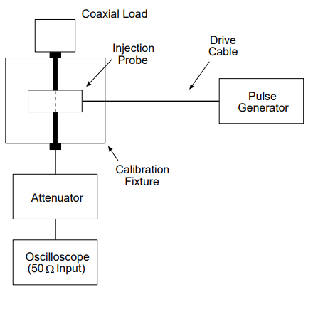
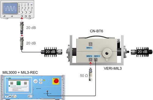
FIGURE CS115-2. Calibration Setup
_20.png "Figure-CS115-2-(1).PNG")
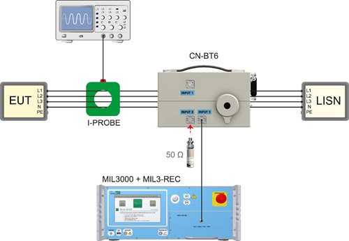
FIGURE CS115-3. Bulk Cable Injection

View CS-115 Calibration
Test Equipment
• Pulse generator, 50 ohm, charged line (coaxial)• Current injection probe
• Drive cable, 50 ohm, 2 meters, 0.5 dB or less insertion loss at 500 MHz
• Current probe
• Calibration fixture: coaxial transmission line with 50 ohm characteristic impedance, coaxial connections on both ends, and space for an injection probe around the center conductor.
• Oscilloscope, 50 ohm input impedance
• Attenuators, 50 ohm
• Coaxial loads, 50 ohm
• LISNs
Procedures
The test procedures shall be as follows:- a. Turn on the measurement equipment and allow sufficient time for stabilization.
- b. Calibration. Perform the following procedures using the calibration setup.
- (1) Adjust the pulse generator source for the rise time, pulse width, and pulse repetition rate requirements specified in the requirement.
- (2) Increase the signal applied to the calibration fixture until the oscilloscope indicates that the current level specified in the requirement exists in the center conductor of the calibration fixture.
- (3) Verify that the rise time, fall time, and pulse width portions of the waveform have the correct durations and that the correct repetition rate is present. The precise pulse shape will not be reproduced due to the inductive coupling mechanism.
- (4) Record the pulse generator amplitude setting.
- c. EUT testing.
- (1) Turn on the EUT and allow sufficient time for stabilization.
- (2) Susceptibility evaluation.
- (a) Adjust the pulse generator, as a minimum, for the amplitude setting determined in 5.13.3.4b(4).
- (b) Apply the test signal at the pulse repetition rate and for the duration specified in the requirement.
- (c) Monitor the EUT for degradation of performance during testing.
- (d) Whenever susceptibility is noted, determine the threshold level in accordance with 4.3.10.4.3.
- (e) Record the peak current induced in the cable as indicated on the oscilloscope.
- (f) Repeat 5.13.3.4c(2)(a) through 5.13.3.4c(2)(e) on each cable bundle interfacing with each electrical connector on the EUT. For power cables, perform 5.13.3.4c(2)(a) through 5.13.3.4c(2)(e) on complete power cables (high sides and returns) and the power cables with the power returns and chassis grounds (green wires) excluded from the cable bundle. For Downloaded from connectors which include both interconnecting leads and power, perform 5.13.3.4c(2)(a) through 5.13.3.4c(2)(e) on the entire bundle, on the power leads (including returns and grounds) grouped separately, and on the power leads grouped with the returns and grounds removed.
Test Setup
The test setup shall be as follows:- a. Maintain a basic test setup for the EUT as shown and described in Figures 2 through 5 and 4.3.8.
- b. Calibration. Configure the test equipment in accordance with Figure CS115-2 for calibrating the injection probe.
- (1) Place the injection probe around the center conductor of the calibration fixture.
- (2) Terminate one end of the calibration fixture with a coaxial load and terminate the other end with an attenuator connected to an oscilloscope with 50 ohm input impedance.
- c. EUT testing. Configure the test equipment as shown in Figure CS115-3 for testing of the EUT.
- (1) Place the injection and monitor probes around a cable bundle interfacing with an EUT connector.
- (2) To minimize errors, maintain the same signal circuit that was used for calibration between the attenuator at the calibration fixture (oscilloscope, coaxial cables, bulkhead connectors, additional attenuators, etc.) and connect the circuit to the monitor probe. Additional attenuation may be used, if necessary.
- (3) Locate the monitor probe 5 cm from the connector. If the overall length of the connector, backshell or backshell extension exceeds 5 cm, position the monitor probe as close to the connector's backshell or backshell extension as possible.
- (4) Position the injection probe 5 cm from the monitor probe.
FIGURE CS115-1. CS115 Signal Characteristics for All Applications
FIGURE CS115-2. Calibration Setup
FIGURE CS115-3. Bulk Cable Injection
Calibration
Cable Bulk Injection
View CS-115 Calibration


