
Standard Overview
MIL-STD-461G CS106 is a military standard test procedure that is used to verify the ability of the EUT to resist transients coupled onto input power leads. The MIL-STD-461 CS106 establishes emission and susceptibility requirements to applicable submarine and surface ship equipment. Additionally, the MIL-STD-461 CS106 can be applied to subsystem AC and DC input power leads. The generator creates a transient pulse in the microsecond range and has repetitions of up to 15 pulses per second. The EUT will not show any signs of malfunction or change from set indications, beyond the tolerances indicated in the individual equipment or subsystem specification when subjected to a test signal with voltage levels as specified in Figure CS106-1, listed below. The 400-volt peak and 5-microsecond pulse is an accurate representation of transients observed on Navy platforms.
Test Equipment
FIGURE CS106-2. Calibration.


CS 106 test setup:

Test Equipment 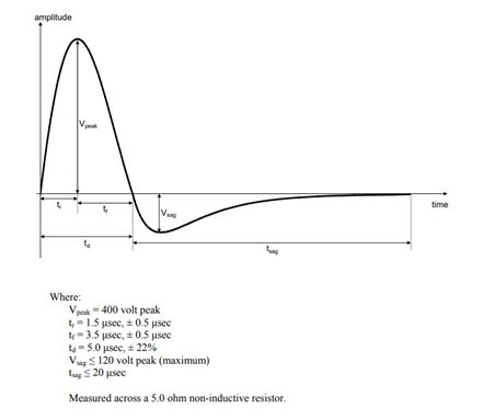_20.jpg "222-(1).jpg")
- Transient generator, ≤ 2 ohm source impedance
- Oscilloscope
- Differential probes
- Isolation transformer
- LISNs
Procedures
The test procedures shall be as follows:- a. Turn on the measurement equipment and allow sufficient time for stabilization.
- b. Calibration
- (1) Set the transient generator to minimum output
- (2) Increase the applied signal until the oscilloscope indicates the voltage level corresponding to the limit. Verify the output waveform and pulse width
- (3) Record the setting of the transient generator
- c. EUT testing
- (1) Turn on the EUT and allow sufficient time for stabilization. CAUTION: Exercise care when performing this test since the "safety ground" of the oscilloscope is disconnected due to the isolation transformer and a shock hazard may be present.
- (2) Set the transient generator to minimum output. Increase the signal level until the required voltage is reached on the power lead or spike generator calibration set point is obtained. Note: Calibration set point is that obtained in 5.11.3.4b(2).
- (3) While maintaining at least the required signal level, apply transient pulses to the test sample’s ungrounded input lines at a pulse repetition rate of between 5 and 10 pulses per second for not less than 5 minutes.
- (4) Susceptibility evaluation.
- (a) Monitor the EUT for degradation of performance.
- (b) If susceptibility is noted, determine and record its threshold level and phase position on the AC waveform in accordance with 4.3.10.4.3 and verify that it is above the limit.
- Repeat 5.11.3.4c(1) through 5.11.3.4c(4) for each power lead and test condition, as required.
TEST Setup
- The test setup shall be as follows:
- a. Maintain a basic test setup for the EUT as shown and described in Figures 2 through 5 and 4.3.8.
- b. Calibration. Configure the test equipment in accordance with Figure CS106-2. Set up the oscilloscope to monitor the specified voltage across the 5 ohm non-inductive resistor.
- c. EUT testing:
- (1) For DC or single phase AC power, configure the test equipment as shown in Figure CS106-3.
- (2) For three phase ungrounded power, configure the test setup as shown in Figure CS106-4.
- (3) For three phase wye power (four power leads), configure the test setup as shown in Figure CS106-5.
FIGURE CS106-2. Calibration.
Calibration
CS 106 calibration setup:
CS 106 test setup:


